-
Part Symbol
-
Footprint
-
3D Model
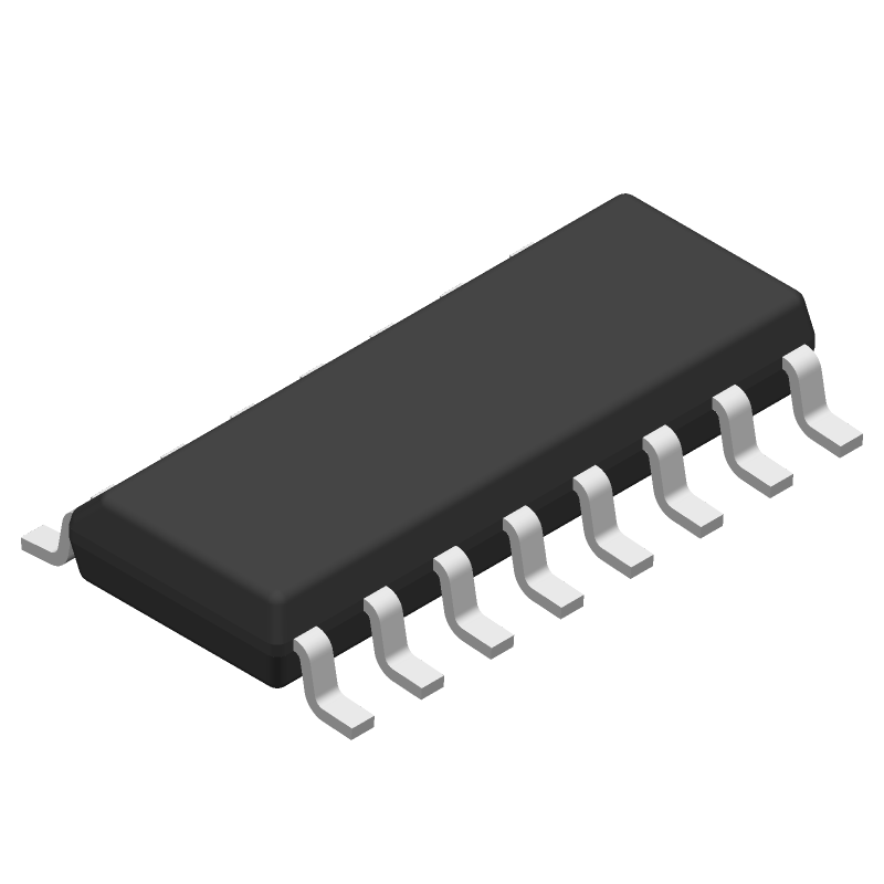
Available Download Formats
By downloading CAD models, you agree to our Terms & Conditions and Privacy Policy

5-V dual channel 120kbps RS-232 line driver/receiver with +/-9V output & +/-15-kV ESD protection 16-SOIC 0 to 70
Tip: Data for a part may vary between manufacturers. You can filter for manufacturers on the top of the page next to the part image and part number.
MAX202CDR by Texas Instruments is a Line Driver or Receiver.
Line Driver or Receivers are under the broader part category of Drivers And Interfaces.
A driver controls the current or voltage delivered to components like LCDs or motors, while an interface component connects systems for data transfer and control. Read more about Drivers And Interfaces on our Drivers And Interfaces part category page.
| Part # | Distributor | Description | Stock | Price | Buy | |
|---|---|---|---|---|---|---|
|
DISTI #
296-18480-1-ND
|
DigiKey | IC TRANSCEIVER FULL 2/2 16SOIC Min Qty: 1 Lead time: 6 Weeks Container: Digi-Reel®, Tape & Reel (TR), Cut Tape (CT) |
7390 In Stock |
|
$0.6044 / $1.3000 | Buy Now |
|
|
Bristol Electronics | 1092 |
|
RFQ | ||
|
|
Quest Components | DUAL LINE TRANSCEIVER, PDSO16 | 2852 |
|
$0.7313 / $2.4375 | Buy Now |
|
|
Quest Components | DUAL LINE TRANSCEIVER, PDSO16 | 997 |
|
$5.5155 / $11.0310 | Buy Now |
By downloading CAD models, you agree to our Terms & Conditions and Privacy Policy
|
|
MAX202CDR
Texas Instruments
Buy Now
Datasheet
|
Compare Parts:
MAX202CDR
Texas Instruments
5-V dual channel 120kbps RS-232 line driver/receiver with +/-9V output & +/-15-kV ESD protection 16-SOIC 0 to 70
|
| Rohs Code | No | |
| Part Life Cycle Code | Obsolete | |
| Ihs Manufacturer | TEXAS INSTRUMENTS INC | |
| Part Package Code | SOIC | |
| Package Description | GREEN, PLASTIC, MS-012AC, SOIC-16 | |
| Pin Count | 16 | |
| Reach Compliance Code | compliant | |
| ECCN Code | EAR99 | |
| HTS Code | 8542.39.00.01 | |
| Samacsys Manufacturer | Texas Instruments | |
| Differential Output | NO | |
| Driver Number of Bits | 2 | |
| High Level Input Current-Max | 0.00001 A | |
| Input Characteristics | SCHMITT TRIGGER | |
| Interface IC Type | LINE TRANSCEIVER | |
| Interface Standard | EIA-232-F; TIA-232-F; V.28 | |
| JESD-30 Code | R-PDSO-G16 | |
| JESD-609 Code | e4 | |
| Length | 9.9 mm | |
| Moisture Sensitivity Level | 1 | |
| Number of Functions | 2 | |
| Number of Terminals | 16 | |
| Operating Temperature-Max | 70 °C | |
| Operating Temperature-Min | ||
| Out Swing-Min | 10 V | |
| Output Low Current-Max | 0.0016 A | |
| Output Polarity | INVERTED | |
| Package Body Material | PLASTIC/EPOXY | |
| Package Code | SOP | |
| Package Equivalence Code | SOP16,.25 | |
| Package Shape | RECTANGULAR | |
| Package Style | SMALL OUTLINE | |
| Peak Reflow Temperature (Cel) | 260 | |
| Qualification Status | Not Qualified | |
| Receive Delay-Max | 10000 ns | |
| Receiver Number of Bits | 2 | |
| Seated Height-Max | 1.75 mm | |
| Supply Current-Max | 15 mA | |
| Supply Voltage-Max | 5.5 V | |
| Supply Voltage-Min | 4.5 V | |
| Supply Voltage-Nom | 5 V | |
| Supply Voltage1-Max | 5.5 V | |
| Supply Voltage1-Min | 4.5 V | |
| Supply Voltage1-Nom | 5 V | |
| Surface Mount | YES | |
| Temperature Grade | COMMERCIAL | |
| Terminal Finish | Nickel/Palladium/Gold (Ni/Pd/Au) | |
| Terminal Form | GULL WING | |
| Terminal Pitch | 1.27 mm | |
| Terminal Position | DUAL | |
| Time@Peak Reflow Temperature-Max (s) | NOT SPECIFIED | |
| Width | 3.9 mm |
This table gives cross-reference parts and alternative options found for MAX202CDR. The Form Fit Function (FFF) tab will give you the options that are more likely to serve as direct pin-to-pin alternates or drop-in parts. The Functional Equivalents tab will give you options that are likely to match the same function of MAX202CDR, but it may not fit your design. Always verify details of parts you are evaluating, as these parts are offered as suggestions for what you are looking for and are not guaranteed.
| Part Number | Manufacturer | Composite Price | Description | Compare |
|---|---|---|---|---|
| MAX202CPW | Texas Instruments | $0.5804 | 5-V dual channel 120kbps RS-232 line driver/receiver with +/-9V output & +/-15-kV ESD protection 16-TSSOP 0 to 70 | MAX202CDR vs MAX202CPW |
| MAX202IDW | Texas Instruments | $0.6764 | 5-V dual channel 120kbps RS-232 line driver/receiver with +/-9V output & +/-15-kV ESD protection 16-SOIC -40 to 85 | MAX202CDR vs MAX202IDW |
| ST232EBN | STMicroelectronics | Check for Price | 15KV ESD PROTECTED 5V RS-232 TRANSCEIVER, [-40oC, 85oC] TEMPERATURE RANGE | MAX202CDR vs ST232EBN |
| ST232EAN | STMicroelectronics | Check for Price | DUAL LINE TRANSCEIVER, PDIP16, 0.250 INCH, PLASTIC, DIP-16 | MAX202CDR vs ST232EAN |
| MAX202CPWG4 | Texas Instruments | Check for Price | 5-V Dual RS-232 Line Driver/Receiver with +/-15 kV ESD Protection 16-TSSOP 0 to 70 | MAX202CDR vs MAX202CPWG4 |
| ST232ECWR | STMicroelectronics | Check for Price | DUAL LINE TRANSCEIVER, PDSO16, ROHS COMPLIANT, SOP-16 | MAX202CDR vs ST232ECWR |
| MAX202IDWRE4 | Texas Instruments | Check for Price | DUAL LINE TRANSCEIVER, PDSO16, GREEN, PLASTIC, SOIC-16 | MAX202CDR vs MAX202IDWRE4 |
| MAX202IPWE4 | Texas Instruments | Check for Price | DUAL LINE TRANSCEIVER, PDSO16, GREEN, PLASTIC, TSSOP-16 | MAX202CDR vs MAX202IPWE4 |
The MAX202CDR requires careful layout and placement to ensure optimal performance. TI recommends placing the device close to the signal source, using short traces, and avoiding vias and right-angle bends. A solid ground plane and decoupling capacitors are also essential.
The MAX202CDR has built-in ESD protection, but additional protection measures can be taken. TI recommends using ESD-protection diodes, such as the TPD2E001, and following proper PCB design and handling practices to prevent ESD damage.
The MAX202CDR is rated for operation from -40°C to 85°C. However, the device's performance may degrade at extreme temperatures. It's essential to ensure proper thermal management and heat dissipation to maintain optimal performance.
Yes, the MAX202CDR is suitable for high-reliability and automotive applications. It meets the requirements of the AEC-Q100 standard and is manufactured using automotive-grade processes. However, additional testing and validation may be required for specific applications.
TI recommends using a systematic approach to troubleshoot issues with the MAX202CDR. Start by verifying the power supply, signal integrity, and PCB layout. Use oscilloscopes and logic analyzers to debug the signal paths. Consult the datasheet and application notes for specific guidance.