-
Part Symbol
-
Footprint
-
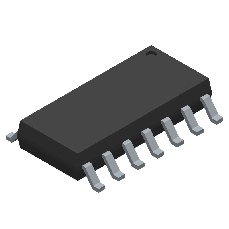
3D Model
Available Download Formats
By downloading CAD models, you agree to our Terms & Conditions and Privacy Policy
20µA, 1/8-Unit-Load, Slew-Rate-Limited, RS-485 Transceivers, 14-SOIC_N-150_MIL, 14 Pins, -40 to 85C
Tip: Data for a part may vary between manufacturers. You can filter for manufacturers on the top of the page next to the part image and part number.
MAX1482ESD+ by Analog Devices Inc is a Line Driver or Receiver.
Line Driver or Receivers are under the broader part category of Drivers And Interfaces.
A driver controls the current or voltage delivered to components like LCDs or motors, while an interface component connects systems for data transfer and control. Read more about Drivers And Interfaces on our Drivers And Interfaces part category page.
| Part # | Distributor | Description | Stock | Price | Buy | |
|---|---|---|---|---|---|---|
|
DISTI #
700-MAX1482ESD
|
Mouser Electronics | RS-422/RS-485 Interface IC 20 A, 1/8-Unit-Load, Slew-Rate-Limited, RS-485 Transceivers RoHS: Compliant | 250 |
|
$3.3600 / $6.1800 | Buy Now |
|
|
Analog Devices Inc | 20µA, 1/8-Unit-Load, Slew-Rate Package Multiple: 1 | 5972 |
|
$3.4951 / $6.1800 | Buy Now |
By downloading CAD models, you agree to our Terms & Conditions and Privacy Policy
|
|
MAX1482ESD+
Analog Devices Inc
Buy Now
Datasheet
|
Compare Parts:
MAX1482ESD+
Analog Devices Inc
20µA, 1/8-Unit-Load, Slew-Rate-Limited, RS-485 Transceivers, 14-SOIC_N-150_MIL, 14 Pins, -40 to 85C
|
| Rohs Code | Yes | |
| Part Life Cycle Code | Active | |
| Ihs Manufacturer | ANALOG DEVICES INC | |
| Part Package Code | 14-SOIC_N-150_MIL | |
| Package Description | 0.150 INCH, LEAD FREE, MS-012AB, SOP-14 | |
| Pin Count | 14 | |
| Manufacturer Package Code | 14-SOIC_N-150_MIL | |
| Reach Compliance Code | compliant | |
| Date Of Intro | 1995-02-01 | |
| Samacsys Manufacturer | Analog Devices | |
| Additional Feature | COMMON I/O; 1 RECEIVER ACTIVE UNDER SHUTDOWN; TRISTATABLE RECEIVER | |
| Differential Output | YES | |
| Driver Number of Bits | 1 | |
| Input Characteristics | DIFFERENTIAL SCHMITT TRIGGER | |
| Interface IC Type | LINE TRANSCEIVER | |
| Interface Standard | EIA-422; EIA-485 | |
| JESD-30 Code | R-PDSO-G14 | |
| JESD-609 Code | e3 | |
| Length | 8.65 mm | |
| Moisture Sensitivity Level | 1 | |
| Number of Functions | 1 | |
| Number of Terminals | 14 | |
| Operating Temperature-Max | 85 °C | |
| Operating Temperature-Min | -40 °C | |
| Out Swing-Min | 5 V | |
| Output Characteristics | 3-STATE | |
| Output Low Current-Max | 0.004 A | |
| Output Polarity | COMPLEMENTARY | |
| Package Body Material | PLASTIC/EPOXY | |
| Package Code | SOP | |
| Package Equivalence Code | SOP14,.25 | |
| Package Shape | RECTANGULAR | |
| Package Style | SMALL OUTLINE | |
| Peak Reflow Temperature (Cel) | 260 | |
| Qualification Status | Not Qualified | |
| Receive Delay-Max | 2250 ns | |
| Receiver Number of Bits | 1 | |
| Seated Height-Max | 1.75 mm | |
| Supply Current-Max | 0.045 mA | |
| Supply Voltage-Max | 5.25 V | |
| Supply Voltage-Min | 4.75 V | |
| Supply Voltage-Nom | 5 V | |
| Surface Mount | YES | |
| Technology | CMOS | |
| Temperature Grade | INDUSTRIAL | |
| Terminal Finish | Matte Tin (Sn) | |
| Terminal Form | GULL WING | |
| Terminal Pitch | 1.27 mm | |
| Terminal Position | DUAL | |
| Time@Peak Reflow Temperature-Max (s) | 30 | |
| Transmit Delay-Max | 2000 ns | |
| Width | 3.9 mm |
This table gives cross-reference parts and alternative options found for MAX1482ESD+. The Form Fit Function (FFF) tab will give you the options that are more likely to serve as direct pin-to-pin alternates or drop-in parts. The Functional Equivalents tab will give you options that are likely to match the same function of MAX1482ESD+, but it may not fit your design. Always verify details of parts you are evaluating, as these parts are offered as suggestions for what you are looking for and are not guaranteed.
| Part Number | Manufacturer | Composite Price | Description | Compare |
|---|---|---|---|---|
| MAX1482CSD | Maxim Integrated Products | Check for Price | Line Transceiver, 1 Func, 1 Driver, 1 Rcvr, CMOS, PDSO14, 0.150 INCH, MS-012AB, SOP-14 | MAX1482ESD+ vs MAX1482CSD |
| MAX1482ESD | Maxim Integrated Products | Check for Price | Line Transceiver, 1 Func, 1 Driver, 1 Rcvr, CMOS, PDSO14, 0.150 INCH, MS-012AB, SOP-14 | MAX1482ESD+ vs MAX1482ESD |
| MAX1482CSD-T | Maxim Integrated Products | Check for Price | Line Transceiver, 1 Func, 1 Driver, 1 Rcvr, CMOS, PDSO14, 0.150 INCH, MS-012AB, SOP-14 | MAX1482ESD+ vs MAX1482CSD-T |
The MAX1482ESD+ datasheet provides general guidelines for layout and placement, but it's recommended to follow Analog Devices' application note AN-1120 for more detailed guidance. This includes keeping the device away from high-current carrying traces, using a solid ground plane, and minimizing the length of the input and output traces.
The MAX1482ESD+ requires a single 5V supply voltage, and it's essential to ensure that the power supply is clean and well-regulated. A decoupling capacitor of 0.1uF to 1uF should be placed close to the device, and the input and output pins should be properly terminated to prevent ringing and reflections.
The MAX1482ESD+ can support data rates up to 100Mbps, but the actual data rate may be limited by the quality of the transmission line, the signal integrity, and the receiver's sensitivity. For high-speed operation, it's essential to ensure that the transmission line is properly terminated, and the signal is properly conditioned to minimize jitter and distortion.
To troubleshoot issues with the MAX1482ESD+, it's essential to follow a systematic approach. Start by verifying the power supply and biasing, then check the signal integrity using an oscilloscope or a signal analyzer. Check for signal reflections, ringing, and jitter, and ensure that the transmission line is properly terminated. If the issue persists, consult the datasheet and application notes for guidance, or contact Analog Devices' technical support.
For high-reliability or high-availability applications, it's essential to follow Analog Devices' guidelines for reliability and quality. This includes ensuring that the device is operated within its recommended operating conditions, using a robust and reliable power supply, and implementing proper thermal management. Additionally, consider using redundant or duplicated circuits to ensure continued operation in the event of a failure.