-
Part Symbol
-
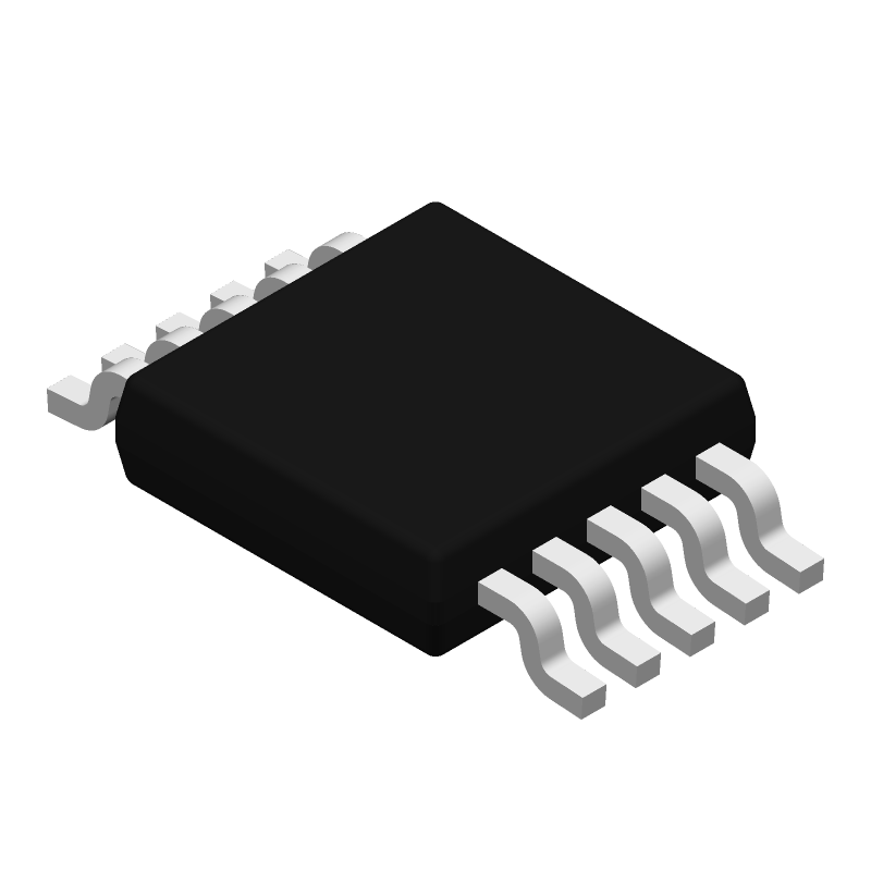
Footprint
-
3D Model
Available Download Formats
By downloading CAD models, you agree to our Terms & Conditions and Privacy Policy

Voltage-to-current converter/transmitter with 3-V to 15-V regulator and resistor set I/O ratio 10-HVSSOP -40 to 125
Tip: Data for a part may vary between manufacturers. You can filter for manufacturers on the top of the page next to the part image and part number.
XTR111AIDGQTG4 by Texas Instruments is an Other Signal Circuit.
Other Signal Circuits are under the broader part category of Signal Circuits.
A signal is an electronic means of transmitting information, either as an analog signal with continuous values or a digital signal with discrete values. Signals are used in various systems and networks. Read more about Signal Circuits on our Signal Circuits part category page.
| Part # | Distributor | Description | Stock | Price | Buy | |
|---|---|---|---|---|---|---|
|
|
Cytech Systems Limited | IC PREC VOLT-CURR CONV/TX 10MSOP | 250 |
|
RFQ | |
|
|
Vyrian | Other Function Semiconductors | 913 |
|
RFQ |
By downloading CAD models, you agree to our Terms & Conditions and Privacy Policy
|
|
XTR111AIDGQTG4
Texas Instruments
Buy Now
Datasheet
|
Compare Parts:
XTR111AIDGQTG4
Texas Instruments
Voltage-to-current converter/transmitter with 3-V to 15-V regulator and resistor set I/O ratio 10-HVSSOP -40 to 125
|
| Rohs Code | No | |
| Part Life Cycle Code | Obsolete | |
| Ihs Manufacturer | TEXAS INSTRUMENTS INC | |
| Part Package Code | MSOP | |
| Package Description | HTSSOP, TSSOP10,.19,20 | |
| Pin Count | 10 | |
| Reach Compliance Code | compliant | |
| ECCN Code | EAR99 | |
| HTS Code | 8542.39.00.01 | |
| Samacsys Manufacturer | Texas Instruments | |
| Analog IC - Other Type | ANALOG CIRCUIT | |
| JESD-30 Code | S-PDSO-G10 | |
| JESD-609 Code | e4 | |
| Length | 3 mm | |
| Moisture Sensitivity Level | 2 | |
| Number of Channels | 1 | |
| Number of Functions | 1 | |
| Number of Terminals | 10 | |
| Operating Temperature-Max | 125 °C | |
| Operating Temperature-Min | -55 °C | |
| Package Body Material | PLASTIC/EPOXY | |
| Package Code | HTSSOP | |
| Package Equivalence Code | TSSOP10,.19,20 | |
| Package Shape | SQUARE | |
| Package Style | SMALL OUTLINE, HEAT SINK/SLUG, THIN PROFILE, SHRINK PITCH | |
| Peak Reflow Temperature (Cel) | 260 | |
| Qualification Status | Not Qualified | |
| Seated Height-Max | 1.1 mm | |
| Supply Current-Max (Isup) | 0.55 mA | |
| Supply Voltage-Max (Vsup) | 40 V | |
| Supply Voltage-Min (Vsup) | 8 V | |
| Supply Voltage-Nom (Vsup) | 24 V | |
| Surface Mount | YES | |
| Technology | BIPOLAR | |
| Temperature Grade | MILITARY | |
| Terminal Finish | Nickel/Palladium/Gold (Ni/Pd/Au) | |
| Terminal Form | GULL WING | |
| Terminal Pitch | 0.5 mm | |
| Terminal Position | DUAL | |
| Time@Peak Reflow Temperature-Max (s) | NOT SPECIFIED | |
| Width | 3 mm |
This table gives cross-reference parts and alternative options found for XTR111AIDGQTG4. The Form Fit Function (FFF) tab will give you the options that are more likely to serve as direct pin-to-pin alternates or drop-in parts. The Functional Equivalents tab will give you options that are likely to match the same function of XTR111AIDGQTG4, but it may not fit your design. Always verify details of parts you are evaluating, as these parts are offered as suggestions for what you are looking for and are not guaranteed.
| Part Number | Manufacturer | Composite Price | Description | Compare |
|---|---|---|---|---|
| XTR111AIDGQR | Texas Instruments | $0.9267 | Voltage-to-current converter/transmitter with 3-V to 15-V regulator and resistor set I/O ratio 10-HVSSOP -40 to 125 | XTR111AIDGQTG4 vs XTR111AIDGQR |
| XTR111AIDGQT | Texas Instruments | $1.8071 | Voltage-to-current converter/transmitter with 3-V to 15-V regulator and resistor set I/O ratio 10-HVSSOP -40 to 125 | XTR111AIDGQTG4 vs XTR111AIDGQT |
| XTR111AIDGQRG4 | Texas Instruments | Check for Price | Voltage-to-current converter/transmitter with 3-V to 15-V regulator and resistor set I/O ratio 10-HVSSOP -40 to 125 | XTR111AIDGQTG4 vs XTR111AIDGQRG4 |
The optimal clock frequency for the XTR111AIDGQTG4 is between 500 MHz to 1 GHz, depending on the specific application and desired performance.
To ensure proper synchronization, use a single clock source for all channels, and ensure that the clock signal is clean and free of jitter. Additionally, use the SYNC pin to synchronize the ADC channels.
The recommended input signal range for the XTR111AIDGQTG4 is between -0.5 V to 2.5 V, with a maximum input signal amplitude of 2 Vpp.
To minimize noise and interference, use proper PCB layout techniques, such as separating analog and digital signals, using ground planes, and adding decoupling capacitors. Additionally, use shielding and filtering to reduce electromagnetic interference (EMI).
The typical power consumption of the XTR111AIDGQTG4 is around 1.2 W at 1 GSPS, with a supply voltage of 1.8 V.