-
Part Symbol
-
Footprint
-
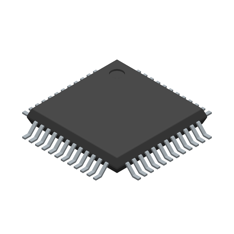
3D Model
Available Download Formats
By downloading CAD models, you agree to our Terms & Conditions and Privacy Policy
Serial I/O Controller, 4 Channel(s), 1.5MBps, CMOS, PQFP48, 7 X 7 MM, 1 MM HEIGHT, GREEN, TQFP-48
Tip: Data for a part may vary between manufacturers. You can filter for manufacturers on the top of the page next to the part image and part number.
XR21V1414IM48-F by MaxLinear Inc is a Serial IO/Communication Controller.
Serial IO/Communication Controllers are under the broader part category of Microcontrollers and Processors.
Microcontrollers (MCUs) are small, low-power integrated circuits used to control embedded systems. Microcontrollers are primarily used to automate and control devices. Read more about Microcontrollers and Processors on our Microcontrollers and Processors part category page.
| Part # | Distributor | Description | Stock | Price | Buy | |
|---|---|---|---|---|---|---|
|
DISTI #
1016-1304-ND
|
DigiKey | IC UART FIFO USB QUAD 48TQFP Min Qty: 1 Lead time: 12 Weeks Container: Tray |
1008 In Stock |
|
$5.5488 / $9.2400 | Buy Now |
|
DISTI #
XR21V1414IM48-F
|
Avnet Americas | - Trays (Alt: XR21V1414IM48-F) RoHS: Compliant Min Qty: 250 Package Multiple: 1 Lead time: 12 Weeks, 0 Days Container: Tray | 2750 |
|
RFQ | |
|
DISTI #
701-XR21V1414IM48-F
|
Mouser Electronics | USB Interface IC 4-Ch 12Mbps 48MHz Internal clock, UART RoHS: Compliant | 4574 |
|
$5.6600 / $9.2400 | Buy Now |
By downloading CAD models, you agree to our Terms & Conditions and Privacy Policy
|
|
XR21V1414IM48-F
MaxLinear Inc
Buy Now
Datasheet
|
Compare Parts:
XR21V1414IM48-F
MaxLinear Inc
Serial I/O Controller, 4 Channel(s), 1.5MBps, CMOS, PQFP48, 7 X 7 MM, 1 MM HEIGHT, GREEN, TQFP-48
|
| Rohs Code | Yes | |
| Part Life Cycle Code | Active | |
| Ihs Manufacturer | MAXLINEAR INC | |
| Package Description | 7 X 7 MM, 1 MM HEIGHT, GREEN, TQFP-48 | |
| Reach Compliance Code | compliant | |
| HTS Code | 8542.31.00.01 | |
| Factory Lead Time | 12 Weeks | |
| Samacsys Manufacturer | MaxLinear, Inc. | |
| Address Bus Width | ||
| Boundary Scan | NO | |
| Bus Compatibility | USB | |
| Clock Frequency-Max | 48 MHz | |
| Communication Protocol | ASYNC, BIT | |
| Data Transfer Rate-Max | 1.5 MBps | |
| External Data Bus Width | ||
| JESD-30 Code | S-PQFP-G48 | |
| JESD-609 Code | e3 | |
| Length | 7 mm | |
| Low Power Mode | YES | |
| Number of Serial I/Os | 4 | |
| Number of Terminals | 48 | |
| Operating Temperature-Max | 85 °C | |
| Operating Temperature-Min | -40 °C | |
| Package Body Material | PLASTIC/EPOXY | |
| Package Code | TFQFP | |
| Package Shape | SQUARE | |
| Package Style | FLATPACK, THIN PROFILE, FINE PITCH | |
| Qualification Status | Not Qualified | |
| Seated Height-Max | 1.2 mm | |
| Supply Voltage-Max | 3.63 V | |
| Supply Voltage-Min | 2.97 V | |
| Supply Voltage-Nom | 3.3 V | |
| Surface Mount | YES | |
| Technology | CMOS | |
| Temperature Grade | INDUSTRIAL | |
| Terminal Finish | Matte Tin (Sn) | |
| Terminal Form | GULL WING | |
| Terminal Pitch | 0.5 mm | |
| Terminal Position | QUAD | |
| Width | 7 mm | |
| uPs/uCs/Peripheral ICs Type | SERIAL IO/COMMUNICATION CONTROLLER, SERIAL |
For optimal performance, it's recommended to follow the PCB layout guidelines provided in the application note AN-215. Ensure a solid ground plane, use thermal vias, and keep the device away from heat sources. A 4-layer PCB with a dedicated power plane and a solid ground plane is recommended.
To optimize power consumption, use the device's built-in power-saving features such as the low-power mode, reduce the clock frequency, and minimize the number of active channels. Additionally, consider using a lower voltage supply and optimizing the PCB design for minimal power loss.
The recommended settings for the internal PLL and clocking system can be found in the device's datasheet and application notes. Typically, the PLL should be set to the desired frequency range, and the clocking system should be configured to minimize jitter and ensure stable operation.
To troubleshoot common issues, start by verifying the device's configuration and settings. Check the signal integrity, clocking, and power supply. Use the device's built-in diagnostic features, such as the error detection and correction mechanisms, to identify and isolate the issue. Consult the datasheet and application notes for specific troubleshooting guidelines.
To prevent ESD damage, handle the device by the body, avoid touching the pins, and use an ESD wrist strap or mat. Store the device in an anti-static bag or container. Follow the recommended handling and storage procedures outlined in the datasheet and industry standards such as ANSI/ESD S20.20.