-
Part Symbol
-
Footprint
-
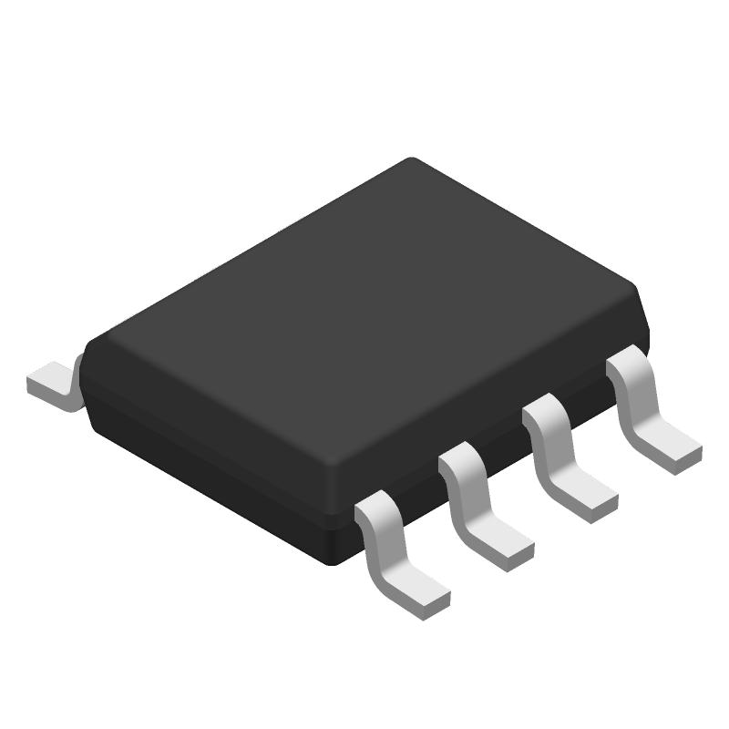
3D Model
Available Download Formats
By downloading CAD models, you agree to our Terms & Conditions and Privacy Policy

Automotive, 20-V, low-power current-mode PWM controller, 14.5-V/9-V UVLO, 100% duty cycle 8-SOIC -40 to 125
Tip: Data for a part may vary between manufacturers. You can filter for manufacturers on the top of the page next to the part image and part number.
UCC28C42QDRQ1 by Texas Instruments is a Switching Regulator or Controller.
Switching Regulator or Controllers are under the broader part category of Power Circuits.
A power circuit delivers electricity in order to operate a load for an electronic device. Power circuits include transformers, generators and switches. Read more about Power Circuits on our Power Circuits part category page.
| Part # | Distributor | Description | Stock | Price | Buy | |
|---|---|---|---|---|---|---|
|
DISTI #
296-UCC28C42QDRQ1CT-ND
|
DigiKey | BICMOS CURRENT MODE PWM CONTROLL Min Qty: 1 Lead time: 12 Weeks Container: Digi-Reel®, Cut Tape (CT), Tape & Reel (TR) |
9333 In Stock |
|
$0.8700 / $1.9100 | Buy Now |
|
DISTI #
595-UCC28C42QDRQ1
|
Mouser Electronics | Switching Controllers Automotive 20-V lo w-power current-mode RoHS: Compliant | 1758 |
|
$0.8700 / $1.9100 | Buy Now |
|
|
Rochester Electronics | UCC28C42-Q1 Automotive BiCMOS low-power current-mode PWM controller RoHS: Compliant Status: Active Min Qty: 1 | 2 |
|
$0.6636 / $1.0700 | Buy Now |
By downloading CAD models, you agree to our Terms & Conditions and Privacy Policy
|
|
UCC28C42QDRQ1
Texas Instruments
Buy Now
Datasheet
|
Compare Parts:
UCC28C42QDRQ1
Texas Instruments
Automotive, 20-V, low-power current-mode PWM controller, 14.5-V/9-V UVLO, 100% duty cycle 8-SOIC -40 to 125
|
| Pbfree Code | Yes | |
| Rohs Code | Yes | |
| Part Life Cycle Code | Active | |
| Ihs Manufacturer | TEXAS INSTRUMENTS INC | |
| Reach Compliance Code | compliant | |
| Date Of Intro | 2017-10-07 | |
| Samacsys Manufacturer | Texas Instruments | |
| Additional Feature | OUTPUT VOLATGE-MAX= 18V; ALSO OPERATES WITH VOLATGE CONTROL MODE | |
| Analog IC - Other Type | SWITCHING CONTROLLER | |
| Control Mode | CURRENT-MODE | |
| Control Technique | PULSE WIDTH MODULATION | |
| Input Voltage-Max | 18 V | |
| Input Voltage-Min | 12 V | |
| Input Voltage-Nom | 15 V | |
| JESD-30 Code | R-PDSO-G8 | |
| JESD-609 Code | e4 | |
| Length | 4.905 mm | |
| Moisture Sensitivity Level | 1 | |
| Number of Functions | 1 | |
| Number of Terminals | 8 | |
| Operating Temperature-Max | 125 °C | |
| Operating Temperature-Min | -40 °C | |
| Output Current-Max | 1 A | |
| Package Body Material | PLASTIC/EPOXY | |
| Package Code | SOP | |
| Package Shape | RECTANGULAR | |
| Package Style | SMALL OUTLINE | |
| Peak Reflow Temperature (Cel) | 260 | |
| Screening Level | AEC-Q100 | |
| Seated Height-Max | 1.75 mm | |
| Supply Voltage-Max (Vsup) | 18 V | |
| Supply Voltage-Min (Vsup) | ||
| Surface Mount | YES | |
| Switcher Configuration | BUCK-BOOST | |
| Switching Frequency-Max | 1000 kHz | |
| Technology | BICMOS | |
| Temperature Grade | AUTOMOTIVE | |
| Terminal Finish | Nickel/Palladium/Gold (Ni/Pd/Au) | |
| Terminal Form | GULL WING | |
| Terminal Pitch | 1.27 mm | |
| Terminal Position | DUAL | |
| Time@Peak Reflow Temperature-Max (s) | 30 | |
| Width | 3.895 mm |
This table gives cross-reference parts and alternative options found for UCC28C42QDRQ1. The Form Fit Function (FFF) tab will give you the options that are more likely to serve as direct pin-to-pin alternates or drop-in parts. The Functional Equivalents tab will give you options that are likely to match the same function of UCC28C42QDRQ1, but it may not fit your design. Always verify details of parts you are evaluating, as these parts are offered as suggestions for what you are looking for and are not guaranteed.
| Part Number | Manufacturer | Composite Price | Description | Compare |
|---|---|---|---|---|
| CS51024ED16 | onsemi | Check for Price | 1A SWITCHING CONTROLLER, 1000kHz SWITCHING FREQ-MAX, PDSO16, SO-16 | UCC28C42QDRQ1 vs CS51024ED16 |
| CS51022D16 | Cherry Semiconductor Corporation | Check for Price | Switching Controller, Current-mode, 1A, 1000kHz Switching Freq-Max, BIPolar, PDSO16, 0.150 INCH, SO-16 | UCC28C42QDRQ1 vs CS51022D16 |
| CS51023AED16 | Cherry Semiconductor Corporation | Check for Price | Switching Controller, Current-mode, 1A, 1000kHz Switching Freq-Max, PDSO16, 0.150 INCH, SO-16 | UCC28C42QDRQ1 vs CS51023AED16 |
| CS51023ED16 | onsemi | Check for Price | 1A SWITCHING CONTROLLER, 1000kHz SWITCHING FREQ-MAX, PDSO16, SO-16 | UCC28C42QDRQ1 vs CS51023ED16 |
| CS51023DR16 | Cherry Semiconductor Corporation | Check for Price | Switching Controller, Current-mode, 1A, 1000kHz Switching Freq-Max, BIPolar, PDSO16, 0.150 INCH, SO-16 | UCC28C42QDRQ1 vs CS51023DR16 |
| CS51021DR16 | Cherry Semiconductor Corporation | Check for Price | Switching Controller, Current-mode, 1A, 1000kHz Switching Freq-Max, BIPolar, PDSO16, 0.150 INCH, SO-16 | UCC28C42QDRQ1 vs CS51021DR16 |
| CS51023D16 | Cherry Semiconductor Corporation | Check for Price | Switching Controller, Current-mode, 1A, 1000kHz Switching Freq-Max, BIPolar, PDSO16, 0.150 INCH, SO-16 | UCC28C42QDRQ1 vs CS51023D16 |
| CS51021D16 | Cherry Semiconductor Corporation | Check for Price | Switching Controller, Current-mode, 1A, 1000kHz Switching Freq-Max, BIPolar, PDSO16, 0.150 INCH, SO-16 | UCC28C42QDRQ1 vs CS51021D16 |
| CS51022ED16 | onsemi | Check for Price | 1A SWITCHING CONTROLLER, 1000kHz SWITCHING FREQ-MAX, PDSO16, SO-16 | UCC28C42QDRQ1 vs CS51022ED16 |
| CS51023AEDR16 | onsemi | Check for Price | 1A SWITCHING CONTROLLER, 1000kHz SWITCHING FREQ-MAX, PDSO16, SOIC-16 | UCC28C42QDRQ1 vs CS51023AEDR16 |
A good thermal design should include a solid ground plane, thermal vias, and a heat sink. The datasheet provides some guidelines, but a more detailed application note (SLUA271) from TI provides additional guidance.
To ensure reliable start-up and shutdown, follow the recommended soft-start and shutdown procedures outlined in the datasheet. Additionally, ensure that the input voltage ramps up and down slowly (e.g., 10-20 ms) to prevent inrush currents and voltage spikes.
When designing an EMI filter, consider the input and output capacitors, inductors, and resistors. Ensure that the filter components are selected to meet the required attenuation and impedance requirements. TI provides an application note (SLUA369) that provides guidance on EMI filter design.
To minimize standby power consumption, ensure that the device is in a low-power mode during standby. This can be achieved by using the EN pin to disable the device, reducing the input voltage, and minimizing the current drawn from the input source.
When designing a thermal solution, consider the device's power dissipation, junction temperature, and thermal resistance. Ensure that the heat sink is properly sized and attached to the device, and that the thermal interface material is suitable for the application.