-
Part Symbol
-
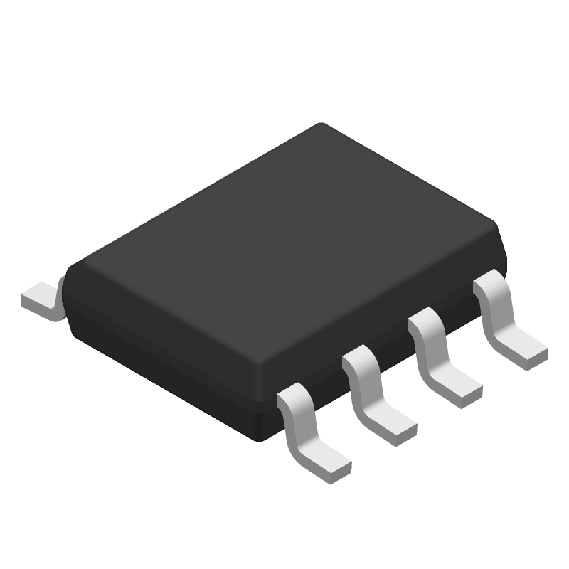
Footprint
-
3D Model
Available Download Formats
By downloading CAD models, you agree to our Terms & Conditions and Privacy Policy

Advanced, self-calibrating, precision, dual operational amplifier 8-SOIC 0 to 70
Tip: Data for a part may vary between manufacturers. You can filter for manufacturers on the top of the page next to the part image and part number.
TLC4502ACDR by Texas Instruments is an Operational Amplifier.
Operational Amplifiers are under the broader part category of Amplifier Circuits.
Amplifier circuits use external power to increase the amplitude of an input signal. They can be used to perform linear amplifications or logarithmic functions. Read more about Amplifier Circuits on our Amplifier Circuits part category page.
| Part # | Distributor | Description | Stock | Price | Buy | |
|---|---|---|---|---|---|---|
|
DISTI #
TLC4502ACDR-ND
|
DigiKey | IC CMOS 2 CIRCUIT 8SOIC Min Qty: 2500 Lead time: 6 Weeks Container: Tape & Reel (TR) | Temporarily Out of Stock |
|
$3.2753 | Buy Now |
|
DISTI #
595-TLC4502ACDR
|
Mouser Electronics | Precision Amplifiers Adv Self-Calib Preci sion Dual A 595-TLC4502ACD RoHS: Compliant | 0 |
|
$3.2700 | Order Now |
|
|
Rochester Electronics | TLC4502A Advanced,Self-Calibrating, Precision, Dual Operational Amplifier RoHS: Compliant Status: Active Min Qty: 1 | 15 |
|
$2.5400 / $3.1800 | Buy Now |
By downloading CAD models, you agree to our Terms & Conditions and Privacy Policy
|
|
TLC4502ACDR
Texas Instruments
Buy Now
Datasheet
|
Compare Parts:
TLC4502ACDR
Texas Instruments
Advanced, self-calibrating, precision, dual operational amplifier 8-SOIC 0 to 70
|
| Pbfree Code | Yes | |
| Rohs Code | Yes | |
| Part Life Cycle Code | Active | |
| Ihs Manufacturer | TEXAS INSTRUMENTS INC | |
| Part Package Code | SOIC | |
| Package Description | SOIC-8 | |
| Pin Count | 8 | |
| Reach Compliance Code | compliant | |
| ECCN Code | EAR99 | |
| HTS Code | 8542.33.00.01 | |
| Samacsys Manufacturer | Texas Instruments | |
| Amplifier Type | OPERATIONAL AMPLIFIER | |
| Architecture | CHOPPER-STAB | |
| Average Bias Current-Max (IIB) | 0.00006 µA | |
| Bias Current-Max (IIB) @25C | 0.00006 µA | |
| Common-mode Reject Ratio-Min | 90 dB | |
| Common-mode Reject Ratio-Nom | 100 dB | |
| Frequency Compensation | YES | |
| Input Offset Current-Max (IIO) | 0.00006 µA | |
| Input Offset Voltage-Max | 50 µV | |
| JESD-30 Code | R-PDSO-G8 | |
| JESD-609 Code | e4 | |
| Length | 4.9 mm | |
| Low-Bias | YES | |
| Low-Offset | YES | |
| Micropower | NO | |
| Moisture Sensitivity Level | 1 | |
| Neg Supply Voltage Limit-Max | ||
| Neg Supply Voltage-Nom (Vsup) | ||
| Number of Functions | 2 | |
| Number of Terminals | 8 | |
| Operating Temperature-Max | 70 °C | |
| Operating Temperature-Min | ||
| Package Body Material | PLASTIC/EPOXY | |
| Package Code | SOP | |
| Package Equivalence Code | SOP8,.25 | |
| Package Shape | RECTANGULAR | |
| Package Style | SMALL OUTLINE | |
| Packing Method | TR | |
| Peak Reflow Temperature (Cel) | 260 | |
| Power | NO | |
| Programmable Power | NO | |
| Qualification Status | Not Qualified | |
| Seated Height-Max | 1.75 mm | |
| Slew Rate-Min | 1 V/us | |
| Slew Rate-Nom | 2.5 V/us | |
| Supply Current-Max | 4 mA | |
| Supply Voltage Limit-Max | 7 V | |
| Supply Voltage-Nom (Vsup) | 5 V | |
| Surface Mount | YES | |
| Technology | CMOS | |
| Temperature Grade | COMMERCIAL | |
| Terminal Finish | Nickel/Palladium/Gold (Ni/Pd/Au) | |
| Terminal Form | GULL WING | |
| Terminal Pitch | 1.27 mm | |
| Terminal Position | DUAL | |
| Time@Peak Reflow Temperature-Max (s) | 30 | |
| Unity Gain BW-Nom | 4700 | |
| Voltage Gain-Min | 200000 | |
| Wideband | NO | |
| Width | 3.9 mm |
This table gives cross-reference parts and alternative options found for TLC4502ACDR. The Form Fit Function (FFF) tab will give you the options that are more likely to serve as direct pin-to-pin alternates or drop-in parts. The Functional Equivalents tab will give you options that are likely to match the same function of TLC4502ACDR, but it may not fit your design. Always verify details of parts you are evaluating, as these parts are offered as suggestions for what you are looking for and are not guaranteed.
| Part Number | Manufacturer | Composite Price | Description | Compare |
|---|---|---|---|---|
| TLC4502AIDR | Texas Instruments | $2.8534 | Advanced, self-calibrating, precision, dual operational amplifier 8-SOIC -40 to 125 | TLC4502ACDR vs TLC4502AIDR |
| TLC4502ACDR | Rochester Electronics LLC | Check for Price | DUAL OP-AMP, 50uV OFFSET-MAX, 4.7MHz BAND WIDTH, PDSO8, GREEN, PLASTIC, SOIC-8 | TLC4502ACDR vs TLC4502ACDR |
| TLC4502ACDG4 | Texas Instruments | Check for Price | Advanced,Self-Calibrating, Precision, Dual Operational Amplifier 8-SOIC 0 to 70 | TLC4502ACDR vs TLC4502ACDG4 |
Texas Instruments recommends a star-connected layout for the TLC4502ACDR, with the device at the center and the input and output pins connected to it. This helps to minimize noise and ensure proper operation. Additionally, it's recommended to use a solid ground plane and to keep the input and output traces as short as possible.
The TLC4502ACDR requires a specific power-up and power-down sequencing to ensure proper operation. The recommended sequence is to power up the VCC pin first, followed by the VIN pin, and then the VREF pin. When powering down, the sequence should be reversed. This helps to prevent latch-up and ensures that the device operates correctly.
The TLC4502ACDR can drive a maximum capacitive load of 100 pF. Exceeding this limit can cause the device to oscillate or become unstable. If a larger capacitive load is required, an external buffer or amplifier may be needed.
The TLC4502ACDR is specified to operate from -40°C to 125°C. To ensure operation within this range, the device should be mounted on a PCB with a thermal pad connected to a solid ground plane. This helps to dissipate heat and maintain a stable temperature. Additionally, the device should be operated within its specified power dissipation limits to prevent overheating.
The recommended input impedance for the TLC4502ACDR is 1 kΩ or higher. This helps to ensure that the device operates within its specified input range and prevents excessive current draw. A lower input impedance can cause the device to become unstable or oscillate.