-
Part Symbol
-
Footprint
-
3D Model
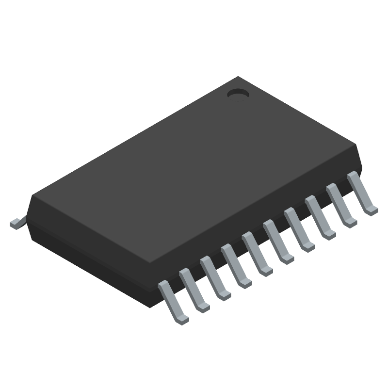
Available Download Formats
By downloading CAD models, you agree to our Terms & Conditions and Privacy Policy

Triple differential transceivers 20-SOIC -40 to 85
Tip: Data for a part may vary between manufacturers. You can filter for manufacturers on the top of the page next to the part image and part number.
SN65LBC171DWR by Texas Instruments is a Line Driver or Receiver.
Line Driver or Receivers are under the broader part category of Drivers And Interfaces.
A driver controls the current or voltage delivered to components like LCDs or motors, while an interface component connects systems for data transfer and control. Read more about Drivers And Interfaces on our Drivers And Interfaces part category page.
| Part # | Distributor | Description | Stock | Price | Buy | |
|---|---|---|---|---|---|---|
|
DISTI #
595-SN65LBC171DWR
|
Mouser Electronics | SCSI Interface IC Triple Differential Transceivers A 595-SN65LBC171DW RoHS: Compliant | 0 |
|
$13.1100 | Order Now |
|
|
Vyrian | Peripheral ICs | 1493 |
|
RFQ |
By downloading CAD models, you agree to our Terms & Conditions and Privacy Policy
|
|
SN65LBC171DWR
Texas Instruments
Buy Now
Datasheet
|
Compare Parts:
SN65LBC171DWR
Texas Instruments
Triple differential transceivers 20-SOIC -40 to 85
|
| Pbfree Code | Yes | |
| Rohs Code | Yes | |
| Part Life Cycle Code | Active | |
| Ihs Manufacturer | TEXAS INSTRUMENTS INC | |
| Part Package Code | SOIC | |
| Package Description | GREEN, PLASTIC, SOIC-20 | |
| Pin Count | 20 | |
| Reach Compliance Code | compliant | |
| ECCN Code | EAR99 | |
| HTS Code | 8542.39.00.60 | |
| Samacsys Manufacturer | Texas Instruments | |
| Differential Output | YES | |
| Driver Number of Bits | 3 | |
| High Level Input Current-Max | 0.0001 A | |
| Input Characteristics | DIFFERENTIAL SCHMITT TRIGGER | |
| Interface IC Type | LINE TRANSCEIVER | |
| Interface Standard | EIA-422; TIA-422; EIA-485; TIA-485; ISO 8482; X3.277 | |
| JESD-30 Code | R-PDSO-G20 | |
| JESD-609 Code | e4 | |
| Length | 12.825 mm | |
| Moisture Sensitivity Level | 1 | |
| Number of Functions | 3 | |
| Number of Terminals | 20 | |
| Operating Temperature-Max | 85 °C | |
| Operating Temperature-Min | -40 °C | |
| Out Swing-Min | 1 V | |
| Output Characteristics | 3-STATE | |
| Output Low Current-Max | 0.0001 A | |
| Output Polarity | TRUE | |
| Package Body Material | PLASTIC/EPOXY | |
| Package Code | SOP | |
| Package Equivalence Code | SOP20,.4 | |
| Package Shape | RECTANGULAR | |
| Package Style | SMALL OUTLINE | |
| Peak Reflow Temperature (Cel) | 260 | |
| Qualification Status | Not Qualified | |
| Receive Delay-Max | 16 ns | |
| Receiver Number of Bits | 3 | |
| Seated Height-Max | 2.65 mm | |
| Supply Current-Max | 20 mA | |
| Supply Voltage-Max | 5.25 V | |
| Supply Voltage-Min | 4.75 V | |
| Supply Voltage-Nom | 5 V | |
| Supply Voltage1-Max | 5.25 V | |
| Supply Voltage1-Min | 4.75 V | |
| Supply Voltage1-Nom | 5 V | |
| Surface Mount | YES | |
| Technology | BICMOS | |
| Temperature Grade | INDUSTRIAL | |
| Terminal Finish | Nickel/Palladium/Gold (Ni/Pd/Au) | |
| Terminal Form | GULL WING | |
| Terminal Pitch | 1.27 mm | |
| Terminal Position | DUAL | |
| Time@Peak Reflow Temperature-Max (s) | 30 | |
| Transmit Delay-Max | 12 ns | |
| Width | 7.5 mm |
This table gives cross-reference parts and alternative options found for SN65LBC171DWR. The Form Fit Function (FFF) tab will give you the options that are more likely to serve as direct pin-to-pin alternates or drop-in parts. The Functional Equivalents tab will give you options that are likely to match the same function of SN65LBC171DWR, but it may not fit your design. Always verify details of parts you are evaluating, as these parts are offered as suggestions for what you are looking for and are not guaranteed.
| Part Number | Manufacturer | Composite Price | Description | Compare |
|---|---|---|---|---|
| SN65LBC171DWRG4 | Texas Instruments | Check for Price | Triple Differential Transceivers 20-SOIC -40 to 85 | SN65LBC171DWR vs SN65LBC171DWRG4 |
Texas Instruments provides a recommended PCB layout in the application note SLVA704, which includes guidelines for trace routing, component placement, and decoupling to minimize EMI and ensure signal integrity.
The termination resistors for the SN65LBC171DWR depend on the specific application and transmission line impedance. TI recommends using the TDR (Time Domain Reflectometry) method to determine the optimal termination resistors. A detailed explanation can be found in the application note SLVA705.
The maximum cable length supported by the SN65LBC171DWR depends on the specific application, cable type, and signal frequency. As a general guideline, TI recommends limiting the cable length to 10 meters for LVDS signals up to 1.5 Gbps. For longer cable lengths, repeaters or active cables may be necessary.
To handle hot swapping with the SN65LBC171DWR, TI recommends using a hot-swap controller, such as the TPS2115A, to control the power sequencing and voltage ramp-up. Additionally, ensure that the device is powered down before disconnecting the cable to prevent damage.
TI recommends powering up the VCC supply before the VCCA supply, and powering down the VCCA supply before the VCC supply. This ensures that the internal voltage regulators are properly sequenced to prevent damage or malfunction.