-
Part Symbol
-
Footprint
-
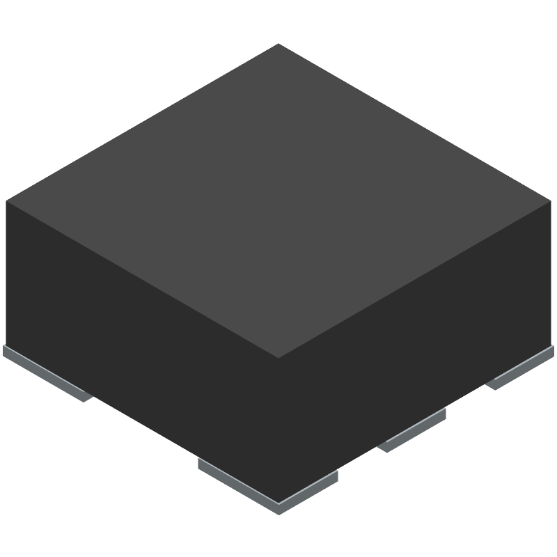
3D Model
Available Download Formats
By downloading CAD models, you agree to our Terms & Conditions and Privacy Policy
SAW Filter, 1 Function(s), 2441.8MHz, 6 Pin(s), Ceramic,
Tip: Data for a part may vary between manufacturers. You can filter for manufacturers on the top of the page next to the part image and part number.
SF2124E by RFM Integrated Device Inc is an SAW Filter.
SAW Filters are under the broader part category of Filters.
A filter is an electronic circuit that selectively allows certain frequencies to pass while attenuating others. They are used to extract desired signals and remove noise. Read more about Filters on our Filters part category page.
| Part # | Distributor | Description | Stock | Price | Buy | |
|---|---|---|---|---|---|---|
|
DISTI #
2410-SF2124ETR2-ND
|
DigiKey | FILTER, SAW, 2441.8 MHZ, 6SMD Min Qty: 10 Lead time: 1 Weeks Container: Tape & Reel (TR), Bag, Tape & Reel (TR) MARKETPLACE PRODUCT | Temporarily Out of Stock |
|
$0.9075 / $1.8800 | Buy Now |
By downloading CAD models, you agree to our Terms & Conditions and Privacy Policy
|
|
SF2124E
RFM Integrated Device Inc
Buy Now
Datasheet
|
Compare Parts:
SF2124E
RFM Integrated Device Inc
SAW Filter, 1 Function(s), 2441.8MHz, 6 Pin(s), Ceramic,
|
| Rohs Code | Yes | |
| Part Life Cycle Code | Contact Manufacturer | |
| Ihs Manufacturer | RFM INTEGRATED DEVICE INC | |
| Reach Compliance Code | compliant | |
| Samacsys Manufacturer | RFMi | |
| Additional Feature | TR, 7 INCH:500 | |
| Center or Cutoff Frequency (fo/fc) | 2441.8 MHz | |
| Filter Type | SAW FILTER | |
| Height | 1.38 mm | |
| Input Impedance | 50 OHM | |
| Insertion Loss-Max | 4 dB | |
| JESD-609 Code | e4 | |
| Length | 3.13 mm | |
| Mounting Type | SURFACE MOUNT | |
| Number of Functions | 1 | |
| Number of Terminals | 6 | |
| Operating Temperature-Max | 125 °C | |
| Operating Temperature-Min | -45 °C | |
| Output Impedance | 50 OHM Ω | |
| Package Material | CERAMIC | |
| Packing Method | TR, 13 INCH | |
| Screening Level | AEC-Q200 | |
| Terminal Finish | Gold (Au) - with Nickel (Ni) barrier | |
| Width | 3.13 mm |
RFM recommends following a 4-layer PCB design with a solid ground plane, using a microstrip or coplanar waveguide layout for the RF signal traces, and keeping the RF signal paths as short as possible. Additionally, decoupling capacitors should be placed close to the device's power pins.
To ensure reliable performance in high-temperature environments, it's essential to follow proper thermal management practices, such as using a heat sink or thermal pad, and ensuring good airflow around the device. Additionally, RFM recommends operating the device within the specified temperature range and avoiding extreme temperature fluctuations.
The internal voltage regulator of the SF2124E can be configured to optimize power consumption. RFM recommends setting the voltage regulator to the lowest possible voltage that meets the system's requirements. Additionally, power consumption can be optimized by using the device's power-down modes, reducing the transmit power, and optimizing the system's overall design.
To troubleshoot and debug issues with the SF2124E, RFM recommends using a logic analyzer or protocol analyzer to monitor the device's digital interfaces, such as SPI or UART. Additionally, checking the device's register settings, transmission power, and antenna design can help identify and resolve issues. RFM also provides a range of development tools and software to aid in debugging and troubleshooting.
When using the SF2124E in a system with multiple antennas, it's essential to ensure proper antenna diversity and switching. RFM recommends using a dedicated antenna switch or multiplexer to connect the antennas to the device. Additionally, optimizing antenna diversity can be achieved by using techniques such as spatial multiplexing, beamforming, or maximal ratio combining.