-
Part Symbol
-
Footprint
-
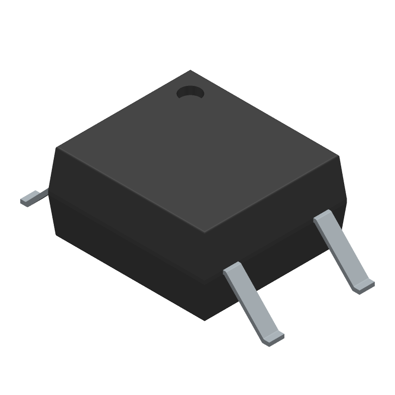
3D Model
Available Download Formats
By downloading CAD models, you agree to our Terms & Conditions and Privacy Policy
1 CHANNEL TRANSISTOR OUTPUT OPTOCOUPLER, ROHS COMPLIANT, PLASTIC, SOP-4
Tip: Data for a part may vary between manufacturers. You can filter for manufacturers on the top of the page next to the part image and part number.
PS2703-1-K-A by Renesas Electronics Corporation is an Optocoupler.
Optocoupler are under the broader part category of Optoelectronics.
Optoelectronic components work to detect, generate, and control light. They can essentially produce and/or react to light. Read more about Optoelectronics on our Optoelectronics part category page.
| Part # | Distributor | Description | Stock | Price | Buy | |
|---|---|---|---|---|---|---|
|
DISTI #
559-1092-ND
|
DigiKey | OPTOISO 3.75KV 1CH TRANS 4-SOP Min Qty: 1 Lead time: 30 Weeks Container: Strip | Temporarily Out of Stock |
|
$0.3020 / $1.0300 | Buy Now |
|
|
Bristol Electronics | 17 |
|
RFQ |
By downloading CAD models, you agree to our Terms & Conditions and Privacy Policy
|
|
PS2703-1-K-A
Renesas Electronics Corporation
Buy Now
Datasheet
|
Compare Parts:
PS2703-1-K-A
Renesas Electronics Corporation
1 CHANNEL TRANSISTOR OUTPUT OPTOCOUPLER, ROHS COMPLIANT, PLASTIC, SOP-4
|
| Pbfree Code | Yes | |
| Rohs Code | Yes | |
| Part Life Cycle Code | Active | |
| Ihs Manufacturer | RENESAS ELECTRONICS CORP | |
| Reach Compliance Code | compliant | |
| HTS Code | 8541.40.80.00 | |
| Samacsys Manufacturer | Renesas Electronics | |
| Current Transfer Ratio-Min | 80% | |
| Forward Current-Max | 0.05 A | |
| Forward Voltage-Max | 1.4 V | |
| Isolation Voltage-Max | 3750 V | |
| Mounting Feature | SURFACE MOUNT | |
| Number of Elements | 1 | |
| On-State Current-Max | 0.03 A | |
| Operating Temperature-Max | 100 °C | |
| Operating Temperature-Min | -55 °C | |
| Power Dissipation-Max | 0.15 W | |
| Surface Mount | YES |
A 4-layer PCB with a solid ground plane and a separate power plane is recommended. Keep the analog and digital sections separate, and use a common ground point for the analog and digital grounds.
Use a metal shield around the device, and ensure a good ground connection. Keep the device away from high-frequency sources, and use a common mode choke or ferrite bead to filter out noise.
Power up the device in the following sequence: VCC, AVCC, and then the input voltage. Ensure a monotonic power-up sequence to prevent latch-up.
Use a heat sink with a thermal resistance of less than 10°C/W. Ensure good airflow around the device, and avoid blocking the airflow with components or obstacles.
Use a pi-filter (C-R-C) or an LC filter with a cutoff frequency of around 100 kHz to filter out noise and ripple.