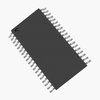
Part Details for PMA5105 by Infineon Technologies AG
Results Overview of PMA5105 by Infineon Technologies AG
- Distributor Offerings: (0 listings)
- Number of FFF Equivalents: (0 replacements)
- CAD Models: (Request Part)
- Number of Functional Equivalents: (0 options)
- Part Data Attributes: (Available)
- Reference Designs: (Not Available)
Tip: Data for a part may vary between manufacturers. You can filter for manufacturers on the top of the page next to the part image and part number.
PMA5105 Information
PMA5105 by Infineon Technologies AG is a Microcontroller.
Microcontrollers are under the broader part category of Microcontrollers and Processors.
Microcontrollers (MCUs) are small, low-power integrated circuits used to control embedded systems. Microcontrollers are primarily used to automate and control devices. Read more about Microcontrollers and Processors on our Microcontrollers and Processors part category page.
Part Details for PMA5105
PMA5105 CAD Models
PMA5105 Part Data Attributes
|
|
PMA5105
Infineon Technologies AG
Buy Now
Datasheet
|
Compare Parts:
PMA5105
Infineon Technologies AG
Microcontroller, 8-Bit, FLASH, 8051 CPU, 12MHz, CMOS, PDSO38, GREEN, PLASTIC, TSSOP-38
|
| Pbfree Code | Yes | |
| Rohs Code | Yes | |
| Part Life Cycle Code | Obsolete | |
| Ihs Manufacturer | INFINEON TECHNOLOGIES AG | |
| Part Package Code | TSSOP | |
| Package Description | GREEN, PLASTIC, TSSOP-38 | |
| Pin Count | 38 | |
| Reach Compliance Code | compliant | |
| HTS Code | 8542.31.00.01 | |
| Has ADC | YES | |
| Address Bus Width | ||
| Bit Size | 8 | |
| CPU Family | 8051 | |
| Clock Frequency-Max | 12 MHz | |
| DAC Channels | NO | |
| DMA Channels | NO | |
| External Data Bus Width | ||
| JESD-30 Code | R-PDSO-G38 | |
| Length | 9.7 mm | |
| Moisture Sensitivity Level | 3 | |
| Number of I/O Lines | 10 | |
| Number of Terminals | 38 | |
| On Chip Program ROM Width | 8 | |
| Operating Temperature-Max | 125 °C | |
| Operating Temperature-Min | -40 °C | |
| PWM Channels | NO | |
| Package Body Material | PLASTIC/EPOXY | |
| Package Code | TSSOP | |
| Package Equivalence Code | TSSOP38,.25,20 | |
| Package Shape | RECTANGULAR | |
| Package Style | SMALL OUTLINE, THIN PROFILE, SHRINK PITCH | |
| Peak Reflow Temperature (Cel) | 260 | |
| Qualification Status | Not Qualified | |
| RAM (bytes) | 256 | |
| ROM (words) | 256 | |
| ROM Programmability | FLASH | |
| Seated Height-Max | 1.2 mm | |
| Speed | 12 MHz | |
| Supply Voltage-Max | 3.6 V | |
| Supply Voltage-Min | 1.9 V | |
| Supply Voltage-Nom | 3 V | |
| Surface Mount | YES | |
| Technology | CMOS | |
| Temperature Grade | AUTOMOTIVE | |
| Terminal Form | GULL WING | |
| Terminal Pitch | 0.5 mm | |
| Terminal Position | DUAL | |
| Width | 4.4 mm | |
| uPs/uCs/Peripheral ICs Type | MICROCONTROLLER |
PMA5105 Frequently Asked Questions (FAQ)
-
Infineon provides a recommended PCB layout in the application note AN2019-01, which includes guidelines for component placement, routing, and thermal management to ensure optimal performance and minimize electromagnetic interference (EMI).
-
The input capacitor selection depends on the input voltage, current, and frequency. A general guideline is to choose a capacitor with a capacitance value between 1uF to 10uF, and a voltage rating that is at least 1.5 times the maximum input voltage. Additionally, consider the capacitor's ESR, ESL, and temperature rating.
-
The maximum allowed voltage drop across the internal switches is typically around 0.5V to 1V, depending on the specific application and operating conditions. Exceeding this voltage drop can lead to reduced efficiency, increased heat generation, and potentially even damage to the device.
-
The PMA5105 has a built-in overcurrent protection feature that can be enabled by connecting the OCP pin to a resistor and capacitor network. The OCP threshold can be adjusted by selecting the appropriate resistor value. Additionally, external overcurrent protection circuits can be implemented using sense resistors and comparators.
-
The PMA5105 is a high-power device that requires effective thermal management to prevent overheating. A recommended strategy is to use a heat sink with a thermal interface material, and to ensure good airflow around the device. The PCB layout should also be designed to minimize thermal resistance and promote heat dissipation.
