-
Part Symbol
-
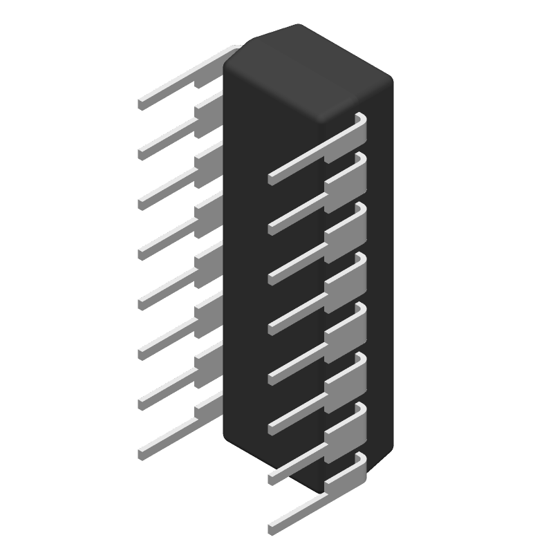
Footprint
-
3D Model
Available Download Formats
By downloading CAD models, you agree to our Terms & Conditions and Privacy Policy

120dB SNR Stereo DAC with BiCMOS Advanced Sign Magnitude Architecture 16-PDIP
Tip: Data for a part may vary between manufacturers. You can filter for manufacturers on the top of the page next to the part image and part number.
PCM1702P-KG4 by Texas Instruments is a Digital to Analog Converter.
Digital to Analog Converters are under the broader part category of Converters.
A converter is an electrical circuit that transforms electric energy into a different form that will support a elecrical load needed by a device. Read more about Converters on our Converters part category page.
| Part # | Distributor | Description | Stock | Price | Buy | |
|---|---|---|---|---|---|---|
|
|
Vyrian | Peripheral ICs | 1020 |
|
RFQ |
By downloading CAD models, you agree to our Terms & Conditions and Privacy Policy
|
|
PCM1702P-KG4
Texas Instruments
Buy Now
Datasheet
|
Compare Parts:
PCM1702P-KG4
Texas Instruments
120dB SNR Stereo DAC with BiCMOS Advanced Sign Magnitude Architecture 16-PDIP
|
| Pbfree Code | No | |
| Rohs Code | Yes | |
| Part Life Cycle Code | Obsolete | |
| Ihs Manufacturer | TEXAS INSTRUMENTS INC | |
| Part Package Code | DIP | |
| Package Description | DIP, DIP16,.3 | |
| Pin Count | 16 | |
| Reach Compliance Code | unknown | |
| HTS Code | 8542.39.00.01 | |
| Samacsys Manufacturer | Texas Instruments | |
| Converter Type | D/A CONVERTER | |
| Input Bit Code | 2'S COMPLEMENT BINARY | |
| Input Format | SERIAL | |
| JESD-30 Code | R-PDIP-T16 | |
| JESD-609 Code | e4 | |
| Length | 19.305 mm | |
| Negative Supply Voltage-Nom | -5 V | |
| Number of Bits | 20 | |
| Number of Functions | 1 | |
| Number of Terminals | 16 | |
| Operating Temperature-Max | 85 °C | |
| Operating Temperature-Min | -25 °C | |
| Package Body Material | PLASTIC/EPOXY | |
| Package Code | DIP | |
| Package Equivalence Code | DIP16,.3 | |
| Package Shape | RECTANGULAR | |
| Package Style | IN-LINE | |
| Qualification Status | Not Qualified | |
| Seated Height-Max | 5.08 mm | |
| Settling Time-Nom (tstl) | 0.2 µs | |
| Supply Voltage-Nom | 5 V | |
| Surface Mount | NO | |
| Technology | BICMOS | |
| Temperature Grade | OTHER | |
| Terminal Finish | NICKEL PALLADIUM GOLD | |
| Terminal Form | THROUGH-HOLE | |
| Terminal Pitch | 2.54 mm | |
| Terminal Position | DUAL | |
| Width | 7.62 mm |
This table gives cross-reference parts and alternative options found for PCM1702P-KG4. The Form Fit Function (FFF) tab will give you the options that are more likely to serve as direct pin-to-pin alternates or drop-in parts. The Functional Equivalents tab will give you options that are likely to match the same function of PCM1702P-KG4, but it may not fit your design. Always verify details of parts you are evaluating, as these parts are offered as suggestions for what you are looking for and are not guaranteed.
| Part Number | Manufacturer | Composite Price | Description | Compare |
|---|---|---|---|---|
| PCM1702PG4 | Texas Instruments | Check for Price | 120dB SNR Stereo DAC with BiCMOS Advanced Sign Magnitude Architecture 16-PDIP | PCM1702P-KG4 vs PCM1702PG4 |
| PCM1702P-J | Texas Instruments | Check for Price | 120dB SNR Stereo DAC with BiCMOS Advanced Sign Magnitude Architecture 16-PDIP | PCM1702P-KG4 vs PCM1702P-J |
| PCM1702P | Texas Instruments | Check for Price | 120dB SNR Stereo DAC with BiCMOS Advanced Sign Magnitude Architecture 16-PDIP | PCM1702P-KG4 vs PCM1702P |
| PCM1702P-K | Texas Instruments | Check for Price | 120dB SNR Stereo DAC with BiCMOS Advanced Sign Magnitude Architecture 16-PDIP | PCM1702P-KG4 vs PCM1702P-K |
The recommended power-up sequence is to apply VCC first, followed by VREF, and then the digital supplies (VDD and VCCO). This ensures that the internal voltage regulators are powered up correctly.
To optimize THD+N performance, ensure that the analog and digital grounds are separated, use a low-noise power supply, and minimize the distance between the PCM1702P-KG4 and the analog signal sources. Additionally, use a high-quality clock source and ensure that the clock frequency is accurate and stable.
The maximum clock frequency that the PCM1702P-KG4 can support is 256 fs (where fs is the sampling frequency). For example, at a sampling frequency of 44.1 kHz, the maximum clock frequency would be 11.2896 MHz.
To configure the PCM1702P-KG4 for master clock mode, connect the MCLK pin to a clock source, and set the M/S pin low. The PCM1702P-KG4 will then generate the internal clock signals from the master clock input.
The recommended layout and routing for the PCM1702P-KG4 involves separating the analog and digital signal paths, using a star-ground configuration, and minimizing the length of the clock signal traces. Additionally, use a solid ground plane and avoid routing digital signals under the analog signal paths.