-
Part Symbol
-
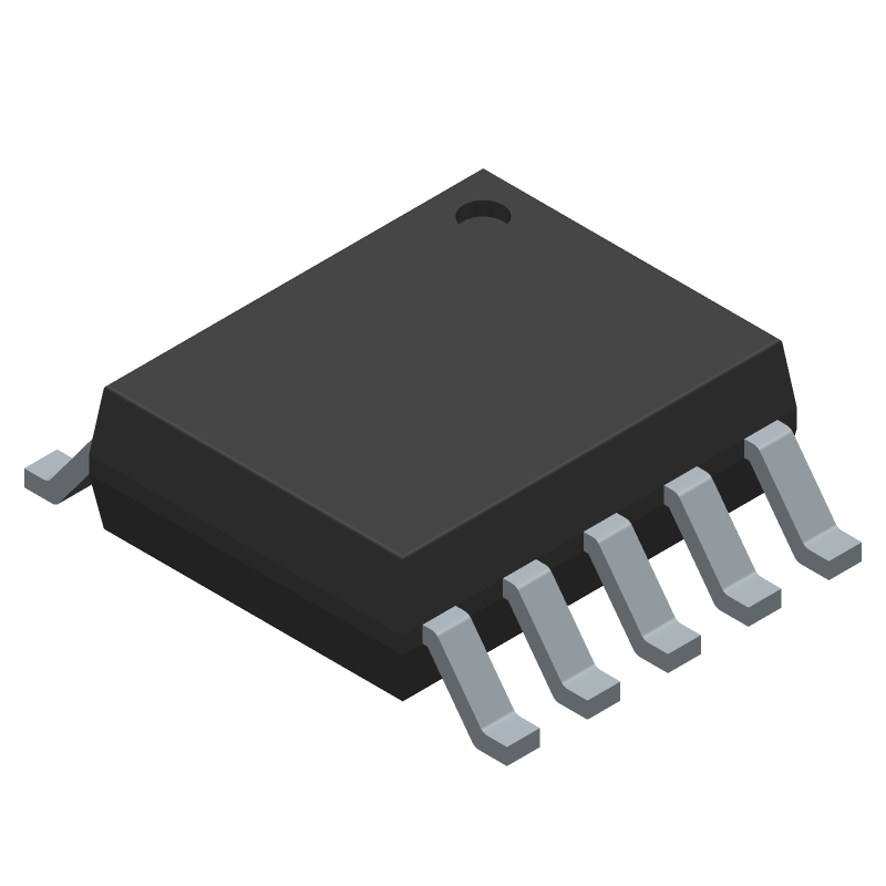
Footprint
-
3D Model
Available Download Formats
By downloading CAD models, you agree to our Terms & Conditions and Privacy Policy
Critical Conduction Mode (CrM) Power Factor Controller and 17 V Startup Level, SOIC-10 NB, 2500-REEL
Tip: Data for a part may vary between manufacturers. You can filter for manufacturers on the top of the page next to the part image and part number.
NCP1612BDR2G by onsemi is a Switching Regulator or Controller.
Switching Regulator or Controllers are under the broader part category of Power Circuits.
A power circuit delivers electricity in order to operate a load for an electronic device. Power circuits include transformers, generators and switches. Read more about Power Circuits on our Power Circuits part category page.
| Part # | Distributor | Description | Stock | Price | Buy | |
|---|---|---|---|---|---|---|
|
DISTI #
NCP1612BDR2GOSCT-ND
|
DigiKey | IC PFC CTRLR CCFF/CRM 10SOIC Min Qty: 1 Lead time: 28 Weeks Container: Cut Tape (CT), Digi-Reel®, Tape & Reel (TR) | Temporarily Out of Stock |
|
$1.6600 | Buy Now |
|
DISTI #
NCP1612BDR2G
|
Avnet Americas | - Tape and Reel (Alt: NCP1612BDR2G) RoHS: Compliant Min Qty: 2500 Package Multiple: 2500 Lead time: 111 Weeks, 0 Days Container: Reel | 0 |
|
RFQ | |
|
|
Cytech Systems Limited | IC PFC CTRLR CCFF/CRM 10SOIC | 625 |
|
RFQ |
By downloading CAD models, you agree to our Terms & Conditions and Privacy Policy
|
|
NCP1612BDR2G
onsemi
Buy Now
Datasheet
|
Compare Parts:
NCP1612BDR2G
onsemi
Critical Conduction Mode (CrM) Power Factor Controller and 17 V Startup Level, SOIC-10 NB, 2500-REEL
|
| Pbfree Code | Yes | |
| Part Life Cycle Code | Obsolete | |
| Ihs Manufacturer | ONSEMI | |
| Part Package Code | SOIC-10 NB | |
| Package Description | SOIC-10 | |
| Pin Count | 10 | |
| Manufacturer Package Code | 751BQ | |
| Reach Compliance Code | compliant | |
| ECCN Code | EAR99 | |
| HTS Code | 8542.39.00.01 | |
| Factory Lead Time | 111 Weeks | |
| Samacsys Manufacturer | onsemi | |
| Analog IC - Other Type | POWER FACTOR CONTROLLER | |
| Control Mode | VOLTAGE-MODE | |
| Control Technique | PULSE WIDTH MODULATION | |
| Input Voltage-Max | 35 V | |
| Input Voltage-Min | 9.5 V | |
| Input Voltage-Nom | 15 V | |
| JESD-30 Code | R-PDSO-G10 | |
| JESD-609 Code | e3 | |
| Length | 4.9 mm | |
| Moisture Sensitivity Level | 1 | |
| Number of Functions | 1 | |
| Number of Terminals | 10 | |
| Operating Temperature-Max | 125 °C | |
| Operating Temperature-Min | -40 °C | |
| Package Body Material | PLASTIC/EPOXY | |
| Package Code | SSOP | |
| Package Equivalence Code | SOP10,.25,40 | |
| Package Shape | RECTANGULAR | |
| Package Style | SMALL OUTLINE, SHRINK PITCH | |
| Peak Reflow Temperature (Cel) | 260 | |
| Qualification Status | Not Qualified | |
| Seated Height-Max | 2 mm | |
| Supply Current-Max (Isup) | 3 mA | |
| Supply Voltage-Nom (Vsup) | 15 V | |
| Surface Mount | YES | |
| Switcher Configuration | BOOST | |
| Temperature Grade | AUTOMOTIVE | |
| Terminal Finish | TIN | |
| Terminal Form | GULL WING | |
| Terminal Pitch | 1 mm | |
| Terminal Position | DUAL | |
| Time@Peak Reflow Temperature-Max (s) | 30 | |
| Width | 3.9 mm |
A good PCB layout for the NCP1612BDR2G should include a solid ground plane, separate analog and digital grounds, and a decoupling capacitor (e.g., 10uF) between VIN and GND. Additionally, keep the input and output capacitors close to the IC and use short, wide traces for the power lines.
Choose X5R or X7R ceramic capacitors with a voltage rating of at least 2x the input voltage. For the input capacitor, a value of 4.7uF to 10uF is recommended. For the output capacitor, a value of 10uF to 22uF is recommended. Ensure the capacitors are placed close to the IC and have a low ESR.
The NCP1612BDR2G is rated for operation from -40°C to +125°C. However, the maximum ambient temperature range depends on the specific application and the device's power dissipation. Consult the datasheet and thermal management guidelines for more information.
To ensure stability, follow the recommended PCB layout, use a sufficient output capacitor, and ensure the input voltage is within the recommended range. Additionally, avoid using long, thin traces for the power lines, and keep the feedback loop as short as possible.
The NCP1612BDR2G is capable of delivering up to 2A of output current. However, the actual output current capability depends on the input voltage, output voltage, and ambient temperature. Consult the datasheet for more information on output current capability and thermal derating.