-
Part Symbol
-
Footprint
-
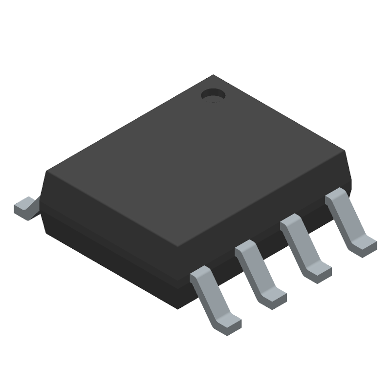
3D Model
Available Download Formats
By downloading CAD models, you agree to our Terms & Conditions and Privacy Policy
Operational Amplifier, 2 Func, 4500uV Offset-Max, CMOS, PDSO8
Tip: Data for a part may vary between manufacturers. You can filter for manufacturers on the top of the page next to the part image and part number.
MCP6002-I/SNVAO by Microchip Technology Inc is an Operational Amplifier.
Operational Amplifiers are under the broader part category of Amplifier Circuits.
Amplifier circuits use external power to increase the amplitude of an input signal. They can be used to perform linear amplifications or logarithmic functions. Read more about Amplifier Circuits on our Amplifier Circuits part category page.
| Part # | Distributor | Description | Stock | Price | Buy | |
|---|---|---|---|---|---|---|
|
DISTI #
150-MCP6002-I/SNVAO-ND
|
DigiKey | IC OPAMP GP 2 CIRCUIT 8SOIC Lead time: 6 Weeks Container: Tube | Temporarily Out of Stock |
|
Buy Now | |
|
DISTI #
MCP6002-I/SNVAO
|
Microchip Technology Inc | Dual 1.8V, 1MHz OP, I temp, SOIC, Projected EOL: 2034-12-07 COO: Thailand ECCN: EAR99 RoHS: Compliant Lead time: 6 Weeks, 0 Days Container: Tube |
0 Alternates Available |
|
$0.3300 / $0.4300 | Buy Now |
|
|
Onlinecomponents.com | Dual Op Amp - Low Power - 1MHz GBP - 1.8 to 6.0 VDC - Rail to Rail I/O - 8-lead SOIC - -40°C to +85°C RoHS: Compliant | 0 |
|
$0 | Buy Now |
|
|
Vyrian | Amplifiers | 1187 |
|
RFQ |
By downloading CAD models, you agree to our Terms & Conditions and Privacy Policy
|
|
MCP6002-I/SNVAO
Microchip Technology Inc
Buy Now
Datasheet
|
Compare Parts:
MCP6002-I/SNVAO
Microchip Technology Inc
Operational Amplifier, 2 Func, 4500uV Offset-Max, CMOS, PDSO8
|
| Rohs Code | Yes | |
| Part Life Cycle Code | Active | |
| Ihs Manufacturer | MICROCHIP TECHNOLOGY INC | |
| Package Description | SOIC-8 | |
| Reach Compliance Code | compliant | |
| ECCN Code | EAR99 | |
| HTS Code | 8542.33.00.01 | |
| Factory Lead Time | 6 Weeks | |
| Samacsys Manufacturer | Microchip | |
| Amplifier Type | OPERATIONAL AMPLIFIER | |
| Architecture | VOLTAGE-FEEDBACK | |
| Common-mode Reject Ratio-Min | 60 dB | |
| Common-mode Reject Ratio-Nom | 76 dB | |
| Frequency Compensation | YES | |
| Input Offset Voltage-Max | 4500 µV | |
| JESD-30 Code | R-PDSO-G8 | |
| JESD-609 Code | e3 | |
| Length | 4.9 mm | |
| Low-Bias | YES | |
| Low-Offset | NO | |
| Micropower | YES | |
| Moisture Sensitivity Level | 1 | |
| Number of Functions | 2 | |
| Number of Terminals | 8 | |
| Operating Temperature-Max | 85 °C | |
| Operating Temperature-Min | -40 °C | |
| Package Body Material | PLASTIC/EPOXY | |
| Package Code | SOP | |
| Package Equivalence Code | SOP8,.25 | |
| Package Shape | RECTANGULAR | |
| Package Style | SMALL OUTLINE | |
| Packing Method | TUBE | |
| Peak Reflow Temperature (Cel) | 260 | |
| Power | NO | |
| Programmable Power | NO | |
| Screening Level | AEC-Q100; TS 16949 | |
| Seated Height-Max | 1.75 mm | |
| Slew Rate-Nom | 0.6 V/us | |
| Supply Current-Max | 0.34 mA | |
| Supply Voltage Limit-Max | 7 V | |
| Supply Voltage-Nom (Vsup) | 5 V | |
| Surface Mount | YES | |
| Technology | CMOS | |
| Temperature Grade | INDUSTRIAL | |
| Terminal Finish | Matte Tin (Sn) | |
| Terminal Form | GULL WING | |
| Terminal Pitch | 1.27 mm | |
| Terminal Position | DUAL | |
| Unity Gain BW-Nom | 1000 | |
| Voltage Gain-Min | 25118.86 | |
| Wideband | NO | |
| Width | 3.9 mm |
The maximum power dissipation of the MCP6002 is 670 mW, which is calculated based on the maximum junction temperature (150°C) and the thermal resistance (125°C/W) of the package.
To ensure stability, it's essential to follow proper layout and grounding techniques, use a low-ESR capacitor for decoupling, and avoid capacitive loads. Additionally, consider adding a small resistor (e.g., 10-50 ohms) in series with the output to improve stability.
The recommended input impedance for the MCP6002 is between 1 kΩ and 100 kΩ. This range ensures optimal performance and minimizes the impact of input bias current on the amplifier's operation.
While the MCP6002 can be used as a comparator, it's not the most suitable application for this op-amp. The MCP6002 is designed for linear amplification, and its performance may not be optimal for comparator applications. Consider using a dedicated comparator IC for such applications.
To ensure ESD protection, follow proper handling and storage procedures for the IC. Use an anti-static wrist strap or mat when handling the device, and store the IC in an anti-static bag or container. Additionally, consider adding external ESD protection components, such as TVS diodes, to the circuit.