-
3D Model
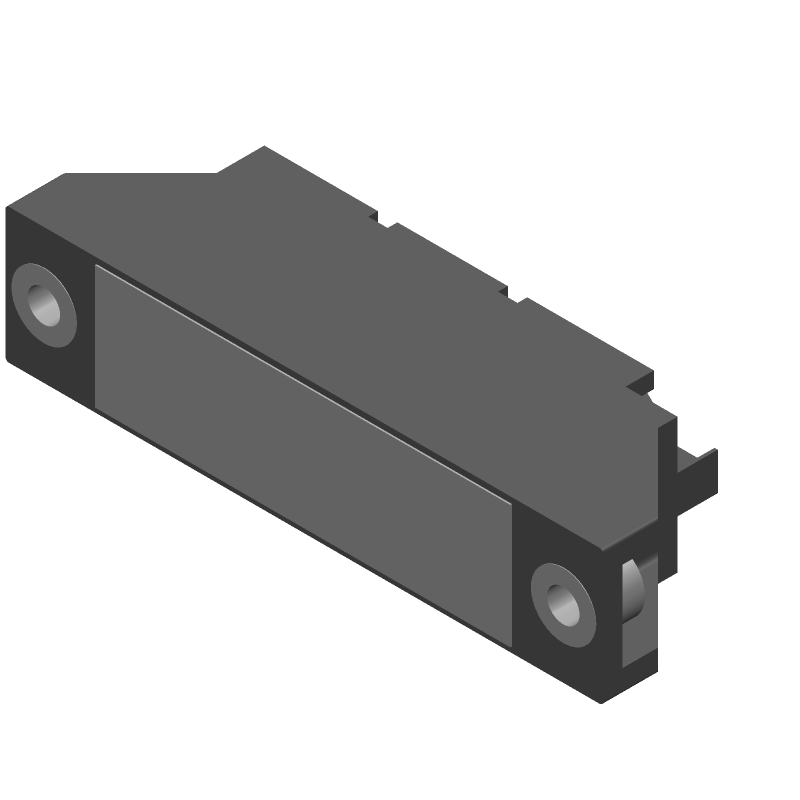
Available Download Formats
By downloading CAD models, you agree to our Terms & Conditions and Privacy Policy
Silicon Controlled Rectifier, 100A I(T)RMS, 60000mA I(T), 1400V V(DRM), 1400V V(RRM), 2 Element, TO-240AA, TO-240AA, 7 PIN
Tip: Data for a part may vary between manufacturers. You can filter for manufacturers on the top of the page next to the part image and part number.
MCC56-14IO1B by Littelfuse Inc is a Silicon Controlled Rectifier.
Silicon Controlled Rectifiers are under the broader part category of Trigger Devices.
Trigger devices initiate or control actions in electronic circuits by producing output signals when specific input conditions are met. They are commonly used in timing circuits and pulse generators. Read more about Trigger Devices on our Trigger Devices part category page.
| Part # | Distributor | Description | Stock | Price | Buy | |
|---|---|---|---|---|---|---|
|
DISTI #
29AK0761
|
Newark | Thyristor Diode Module, 0.1A, 1.5V Rohs Compliant: Yes |Littelfuse MCC56-14IO1B RoHS: Compliant Min Qty: 1 Package Multiple: 1 Date Code: 1 Container: Bulk | 23 |
|
$21.2400 / $32.8100 | Buy Now |
By downloading CAD models, you agree to our Terms & Conditions and Privacy Policy
|
|
MCC56-14IO1B
Littelfuse Inc
Buy Now
Datasheet
|
Compare Parts:
MCC56-14IO1B
Littelfuse Inc
Silicon Controlled Rectifier, 100A I(T)RMS, 60000mA I(T), 1400V V(DRM), 1400V V(RRM), 2 Element, TO-240AA, TO-240AA, 7 PIN
|
| Rohs Code | Yes | |
| Part Life Cycle Code | Active | |
| Ihs Manufacturer | LITTELFUSE INC | |
| Package Description | TO-240AA, 7 PIN | |
| Reach Compliance Code | compliant | |
| ECCN Code | EAR99 | |
| HTS Code | 8541.30.00.80 | |
| Samacsys Manufacturer | LITTELFUSE | |
| Case Connection | ISOLATED | |
| Configuration | SERIES CONNECTED, CENTER TAP, 2 ELEMENTS | |
| DC Gate Trigger Current-Max | 100 mA | |
| DC Gate Trigger Voltage-Max | 1.5 V | |
| Desc. of Quick-Connects | 2G-2GR | |
| Desc. of Screw Terminals | A-K-AK | |
| Holding Current-Max | 200 mA | |
| JEDEC-95 Code | TO-240AA | |
| JESD-30 Code | R-XUFM-X7 | |
| Leakage Current-Max | 15 mA | |
| Non-Repetitive Pk On-state Cur | 1600 A | |
| Number of Elements | 2 | |
| Number of Terminals | 7 | |
| On-state Current-Max | 60000 A | |
| Operating Temperature-Max | 125 °C | |
| Operating Temperature-Min | -40 °C | |
| Package Body Material | UNSPECIFIED | |
| Package Shape | RECTANGULAR | |
| Package Style | FLANGE MOUNT | |
| Peak Reflow Temperature (Cel) | NOT SPECIFIED | |
| Qualification Status | Not Qualified | |
| RMS On-state Current-Max | 100 A | |
| Reference Standard | UL RECOGNIZED | |
| Repetitive Peak Off-state Voltage | 1400 V | |
| Repetitive Peak Reverse Voltage | 1400 V | |
| Surface Mount | NO | |
| Terminal Form | UNSPECIFIED | |
| Terminal Position | UPPER | |
| Time@Peak Reflow Temperature-Max (s) | NOT SPECIFIED | |
| Trigger Device Type | SCR |
For optimal performance, it is recommended to follow the PCB layout guidelines provided in the datasheet, including keeping the input and output traces separate, using a solid ground plane, and placing the device near a heat sink or thermal pad. Additionally, ensure good airflow around the device and avoid placing heat-generating components nearby.
To ensure EMC, follow proper PCB design and layout practices, such as using shielding, filtering, and grounding techniques. Additionally, consider using a metal enclosure or shielded cables to minimize electromagnetic radiation. It is also recommended to perform EMC testing to ensure compliance with relevant standards.
The maximum operating temperature range for the MCC56-14IO1B is -40°C to 125°C. However, it is recommended to derate the device's performance at higher temperatures to ensure reliability and longevity.
Yes, the MCC56-14IO1B is designed to withstand high-vibration and high-shock environments. However, it is recommended to follow proper mounting and installation procedures, and to ensure that the device is securely fastened to the PCB or chassis to prevent damage or dislodging.
To troubleshoot common issues with the MCC56-14IO1B, refer to the datasheet and application notes for guidance. Common causes of output voltage deviations include incorrect input voltage, incorrect output voltage setting, or excessive output current. Overheating can be caused by excessive ambient temperature, poor airflow, or high output current. Use a multimeter and oscilloscope to measure voltage and current, and consult the datasheet for troubleshooting flowcharts and guidelines.