-
Part Symbol
-
Footprint
-
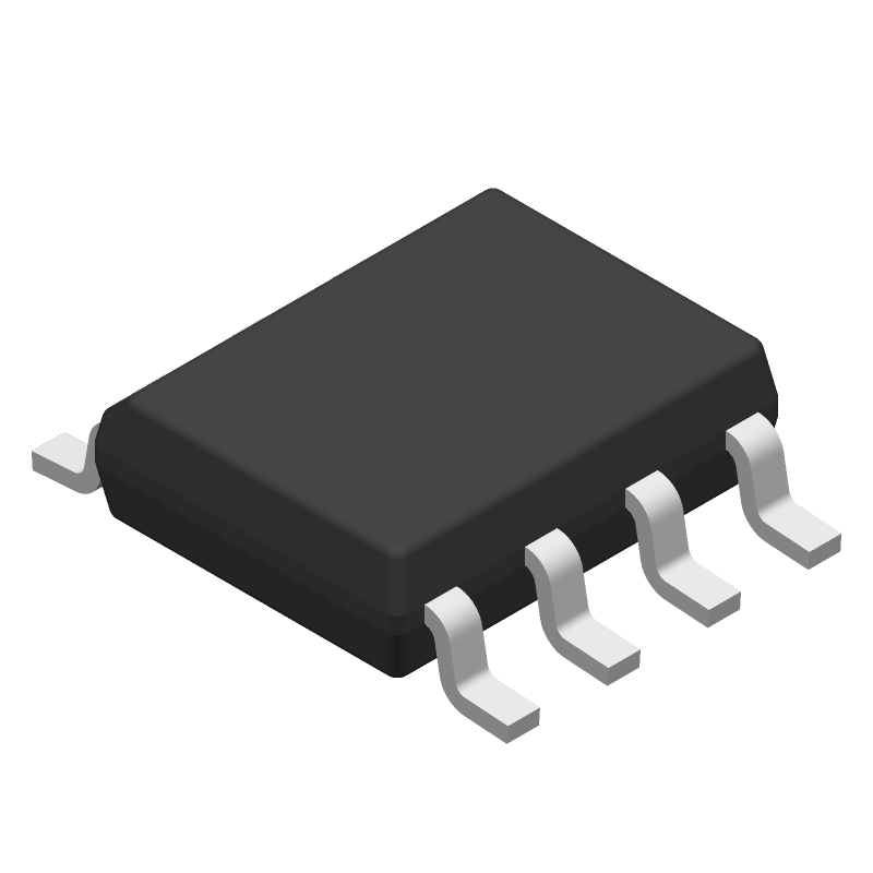
3D Model
Available Download Formats
By downloading CAD models, you agree to our Terms & Conditions and Privacy Policy

1.5-A boost, buck, inverting switching regulator, operation from -40°C to 85°C 8-SOIC -40 to 85
Tip: Data for a part may vary between manufacturers. You can filter for manufacturers on the top of the page next to the part image and part number.
MC33063ADE4 by Texas Instruments is a Switching Regulator or Controller.
Switching Regulator or Controllers are under the broader part category of Power Circuits.
A power circuit delivers electricity in order to operate a load for an electronic device. Power circuits include transformers, generators and switches. Read more about Power Circuits on our Power Circuits part category page.
| Part # | Distributor | Description | Stock | Price | Buy | |
|---|---|---|---|---|---|---|
|
DISTI #
595-MC33063ADE4
|
Mouser Electronics | Switching Voltage Regulators 1.5-A Peak Boost/ Bu ck/Inverting Swit ALT 595-MC33063AD RoHS: Compliant | 2504 |
|
$0.6760 / $2.3200 | Buy Now |
|
|
Vyrian | Other Function Semiconductors | 1530 |
|
RFQ |
By downloading CAD models, you agree to our Terms & Conditions and Privacy Policy
|
|
MC33063ADE4
Texas Instruments
Buy Now
Datasheet
|
Compare Parts:
MC33063ADE4
Texas Instruments
1.5-A boost, buck, inverting switching regulator, operation from -40°C to 85°C 8-SOIC -40 to 85
|
| Pbfree Code | Yes | |
| Rohs Code | Yes | |
| Part Life Cycle Code | Active | |
| Ihs Manufacturer | TEXAS INSTRUMENTS INC | |
| Part Package Code | SOIC | |
| Package Description | GREEN, PLASTIC, MS-012AA, SOIC-8 | |
| Pin Count | 8 | |
| Reach Compliance Code | compliant | |
| ECCN Code | EAR99 | |
| HTS Code | 8542.39.00.01 | |
| Samacsys Manufacturer | Texas Instruments | |
| Analog IC - Other Type | SWITCHING CONTROLLER | |
| Control Mode | VOLTAGE-MODE | |
| Control Technique | PULSE WIDTH MODULATION | |
| Input Voltage-Max | 40 V | |
| Input Voltage-Min | 3 V | |
| Input Voltage-Nom | 5 V | |
| JESD-30 Code | R-PDSO-G8 | |
| JESD-609 Code | e4 | |
| Length | 4.9 mm | |
| Moisture Sensitivity Level | 1 | |
| Number of Functions | 1 | |
| Number of Outputs | 1 | |
| Number of Terminals | 8 | |
| Operating Temperature-Max | 85 °C | |
| Operating Temperature-Min | -40 °C | |
| Output Current-Max | 1.5 A | |
| Output Voltage-Max | 40 V | |
| Output Voltage-Min | 1.25 V | |
| Package Body Material | PLASTIC/EPOXY | |
| Package Code | SOP | |
| Package Equivalence Code | SOP8,.25 | |
| Package Shape | RECTANGULAR | |
| Package Style | SMALL OUTLINE | |
| Peak Reflow Temperature (Cel) | 260 | |
| Qualification Status | Not Qualified | |
| Seated Height-Max | 1.75 mm | |
| Supply Current-Max (Isup) | 4 mA | |
| Supply Voltage-Nom (Vsup) | 5 V | |
| Surface Mount | YES | |
| Switcher Configuration | BUCK-BOOST | |
| Switching Frequency-Max | 100 kHz | |
| Technology | BIPOLAR | |
| Temperature Grade | INDUSTRIAL | |
| Terminal Finish | Nickel/Palladium/Gold (Ni/Pd/Au) | |
| Terminal Form | GULL WING | |
| Terminal Pitch | 1.27 mm | |
| Terminal Position | DUAL | |
| Time@Peak Reflow Temperature-Max (s) | 30 | |
| Width | 3.9 mm |
This table gives cross-reference parts and alternative options found for MC33063ADE4. The Form Fit Function (FFF) tab will give you the options that are more likely to serve as direct pin-to-pin alternates or drop-in parts. The Functional Equivalents tab will give you options that are likely to match the same function of MC33063ADE4, but it may not fit your design. Always verify details of parts you are evaluating, as these parts are offered as suggestions for what you are looking for and are not guaranteed.
| Part Number | Manufacturer | Composite Price | Description | Compare |
|---|---|---|---|---|
| MC33063ADG | onsemi | $0.3790 | Buck / Boost / Inverting Regulator, Switching, 1.5 A TA= -40°C to 85°C, SOIC-8 Narrow Body, 98-TUBE | MC33063ADE4 vs MC33063ADG |
| MC34063EBD | STMicroelectronics | Check for Price | DC-DC CONVERTER CONTROL CIRCUITS | MC33063ADE4 vs MC34063EBD |
| MC33063ADR2 | Motorola Mobility LLC | Check for Price | 1.5A SWITCHING REGULATOR, 100kHz SWITCHING FREQ-MAX, PDSO8, PLASTIC, SO-8 | MC33063ADE4 vs MC33063ADR2 |
| SP34063AEN/TR | Sipex Corporation | Check for Price | Switching Regulator, 1.5A, 110kHz Switching Freq-Max, PDSO8, MO-012-AA, NSOIC-8 | MC33063ADE4 vs SP34063AEN/TR |
| MC33063ADX | onsemi | Check for Price | Buck / Boost / Inverting Regulator, Switching, 1.5 A, 3000-REEL | MC33063ADE4 vs MC33063ADX |
| SP34063AEN-L/TR | MaxLinear Inc | Check for Price | Switching Regulator, 1.5A, 110kHz Switching Freq-Max, PDSO8, LEAD FREE, MS-012AA, NSOIC-8 | MC33063ADE4 vs SP34063AEN-L/TR |
| MC34063ADX | Rochester Electronics LLC | Check for Price | 1.5A SWITCHING REGULATOR, 100kHz SWITCHING FREQ-MAX, PDSO8, SOP-8 | MC33063ADE4 vs MC34063ADX |
| MC34063ADX | Fairchild Semiconductor Corporation | Check for Price | Switching Regulator, Voltage-mode, 1.5A, 100kHz Switching Freq-Max, BIPolar, PDSO8, SOP-8 | MC33063ADE4 vs MC34063ADX |
| KA34063AD | Fairchild Semiconductor Corporation | Check for Price | Switching Regulator, Voltage-mode, 1.5A, 100kHz Switching Freq-Max, BIPolar, PDSO8, SOP-8 | MC33063ADE4 vs KA34063AD |
| MC34063ADR2 | Rochester Electronics LLC | Check for Price | 1.5A SWITCHING REGULATOR, 100kHz SWITCHING FREQ-MAX, PDSO8, SOIC-8 | MC33063ADE4 vs MC34063ADR2 |
The maximum input voltage that can be applied to the MC33063ADE4 is 40V, but it's recommended to keep it below 35V for reliable operation.
To ensure CCM operation, the inductor value should be chosen such that the inductor current ripple is less than 30% of the output current. Additionally, the output capacitor should be large enough to filter the output voltage ripple.
The bootstrap capacitor (CBOOT) is used to generate the gate drive voltage for the internal power MOSFET. It's essential to choose a capacitor with a high voltage rating and low ESR to ensure reliable operation.
The minimum input capacitance can be calculated using the formula: Cin(min) = (Iout x Vout) / (fsw x ΔV). Where Iout is the output current, Vout is the output voltage, fsw is the switching frequency, and ΔV is the input voltage ripple.
The recommended layout and placement for the MC33063ADE4 involves keeping the power components (inductor, capacitor, and MOSFET) close together, using a solid ground plane, and minimizing the length of the high-current paths. Additionally, the input and output capacitors should be placed close to the IC.