-
Part Symbol
-
Footprint
Available Download Formats
By downloading CAD models, you agree to our Terms & Conditions and Privacy Policy

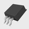
Schottky Barrier Rectifier, 15 V, 25 A, D2PAK 2 LEAD, 50-TUBE
Tip: Data for a part may vary between manufacturers. You can filter for manufacturers on the top of the page next to the part image and part number.
MBRB2515L by onsemi is a Rectifier Diode.
Rectifier Diodes are under the broader part category of Diodes.
A diode is a electrical part that can control the direction in which the current flows in a device. Consider factors like voltage drop, current capacity, reverse voltage, and operating frequency when selecting a diode. Read more about Diodes on our Diodes part category page.
| Part # | Distributor | Description | Stock | Price | Buy | |
|---|---|---|---|---|---|---|
|
|
Bristol Electronics | 9655 |
|
RFQ | ||
|
|
Bristol Electronics | 140 |
|
RFQ | ||
|
|
Quest Components | 25 A, 15 V, SILICON, RECTIFIER DIODE | 836 |
|
$0.8400 / $2.1000 | Buy Now |
|
|
Quest Components | 25 A, 15 V, SILICON, RECTIFIER DIODE | 66 |
|
$0.8813 / $1.4688 | Buy Now |
|
|
Component Electronics, Inc | IN STOCK SHIP TODAY | 36 |
|
$1.7500 / $2.6900 | Buy Now |
|
|
Win Source Electronics | DIODE SCHOTTKY 15V 25A D2PAK | 2200 |
|
$1.6283 / $2.4426 | Buy Now |
By downloading CAD models, you agree to our Terms & Conditions and Privacy Policy
|
|
MBRB2515L
onsemi
Buy Now
Datasheet
|
Compare Parts:
MBRB2515L
onsemi
Schottky Barrier Rectifier, 15 V, 25 A, D2PAK 2 LEAD, 50-TUBE
|
| Pbfree Code | No | |
| Rohs Code | No | |
| Part Life Cycle Code | Obsolete | |
| Ihs Manufacturer | ONSEMI | |
| Part Package Code | D2PAK 2 LEAD | |
| Pin Count | 3 | |
| Manufacturer Package Code | 418B-04 | |
| Reach Compliance Code | not_compliant | |
| ECCN Code | EAR99 | |
| HTS Code | 8541.10.00.80 | |
| Factory Lead Time | 4 Weeks | |
| Samacsys Manufacturer | onsemi | |
| Additional Feature | FREE WHEELING DIODE | |
| Application | POWER | |
| Case Connection | CATHODE | |
| Configuration | SINGLE | |
| Diode Element Material | SILICON | |
| Diode Type | RECTIFIER DIODE | |
| Forward Voltage-Max (VF) | 0.45 V | |
| JESD-30 Code | R-PSSO-G2 | |
| JESD-609 Code | e0 | |
| Moisture Sensitivity Level | 1 | |
| Non-rep Pk Forward Current-Max | 150 A | |
| Number of Elements | 1 | |
| Number of Phases | 1 | |
| Number of Terminals | 2 | |
| Operating Temperature-Max | 100 °C | |
| Output Current-Max | 25 A | |
| Package Body Material | PLASTIC/EPOXY | |
| Package Shape | RECTANGULAR | |
| Package Style | SMALL OUTLINE | |
| Peak Reflow Temperature (Cel) | 235 | |
| Qualification Status | Not Qualified | |
| Rep Pk Reverse Voltage-Max | 15 V | |
| Surface Mount | YES | |
| Technology | SCHOTTKY | |
| Terminal Finish | Tin/Lead (Sn/Pb) | |
| Terminal Form | GULL WING | |
| Terminal Position | SINGLE | |
| Time@Peak Reflow Temperature-Max (s) | 30 |
The recommended PCB layout for optimal thermal performance involves placing a thermal pad on the bottom of the device, using a minimum of 2 oz copper thickness, and ensuring a solid copper fill around the device. Additionally, it's recommended to use vias to connect the thermal pad to an internal copper plane or the backside of the PCB to dissipate heat efficiently.
To ensure the device is properly biased, make sure to follow the recommended operating conditions in the datasheet, including the input voltage range, output voltage range, and current limits. Additionally, ensure that the input and output capacitors are properly sized and placed close to the device to minimize parasitic inductance and resistance.
To prevent damage, handle the device by the body and avoid touching the leads or pins. Use an anti-static wrist strap or mat to prevent electrostatic discharge (ESD) damage. Avoid bending or flexing the leads, and ensure that the device is stored in a dry, cool place away from direct sunlight.
Yes, the MBRB2515L is suitable for high-reliability and automotive applications. It meets the requirements of AEC-Q101, which is a standard for automotive-grade semiconductor devices. However, it's essential to follow the recommended operating conditions, storage, and handling procedures to ensure the device meets the required reliability and quality standards.
To troubleshoot issues with the device, start by reviewing the datasheet and application notes to ensure that the device is properly biased and operated within the recommended conditions. Check for signs of physical damage, such as cracks or corrosion, and verify that the PCB layout and thermal design are correct. Use oscilloscopes or other diagnostic tools to measure the input and output waveforms, and consult with onsemi's technical support team if the issue persists.