-
Part Symbol
-
Footprint
-
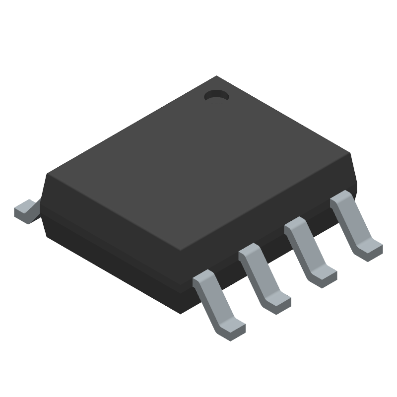
3D Model
Available Download Formats
By downloading CAD models, you agree to our Terms & Conditions and Privacy Policy
+5V to ±10V Voltage Converters, 8-SOIC_N-150_MIL, 8 Pins, 0 to 70C
Tip: Data for a part may vary between manufacturers. You can filter for manufacturers on the top of the page next to the part image and part number.
MAX680CSA+ by Analog Devices Inc is a Switching Regulator or Controller.
Switching Regulator or Controllers are under the broader part category of Power Circuits.
A power circuit delivers electricity in order to operate a load for an electronic device. Power circuits include transformers, generators and switches. Read more about Power Circuits on our Power Circuits part category page.
| Part # | Distributor | Description | Stock | Price | Buy | |
|---|---|---|---|---|---|---|
|
DISTI #
81Y9558
|
Newark | Dc-Dc Charge Pump, Boost/Inv, 70Deg C, Ic Case/Package:Nsoic, No. Of Pins:8Pins, Output Current Max:10Ma, Fixed Output Voltage Nom:-, Adjustable Output Voltage Min:-12V, Adjustable Output Voltage Max:-, Input Voltage Min:2V Rohs Compliant: Yes |Analog Devices MAX680CSA+ RoHS: Compliant Min Qty: 1 Package Multiple: 1 Date Code: 1 Container: Bulk | 101 |
|
$3.8900 / $5.4600 | Buy Now |
|
DISTI #
700-MAX680CSA
|
Mouser Electronics | Switching Voltage Regulators +5V to 10V Voltage Converters RoHS: Compliant | 290 |
|
$3.8500 / $6.2600 | Buy Now |
|
|
Analog Devices Inc | +5V to ±10V Voltage Converters Package Multiple: 1 | 987 |
|
$2.9700 / $8.5600 | Buy Now |
|
DISTI #
MAX680CSA+
|
TME | PMIC, DC/DC converter, Uin: 2÷6VDC, Uout: -10÷5VDC, 10mA, SO8, SMD Min Qty: 1 | 18 |
|
$3.9500 / $5.5300 | Buy Now |
By downloading CAD models, you agree to our Terms & Conditions and Privacy Policy
|
|
MAX680CSA+
Analog Devices Inc
Buy Now
Datasheet
|
Compare Parts:
MAX680CSA+
Analog Devices Inc
+5V to ±10V Voltage Converters, 8-SOIC_N-150_MIL, 8 Pins, 0 to 70C
|
| Rohs Code | Yes | |
| Part Life Cycle Code | Active | |
| Ihs Manufacturer | ANALOG DEVICES INC | |
| Part Package Code | 8-SOIC_N-150_MIL | |
| Package Description | 0.150 INCH, SOP-8 | |
| Pin Count | 8 | |
| Manufacturer Package Code | 8-SOIC_N-150_MIL | |
| Reach Compliance Code | compliant | |
| Date Of Intro | 1996-11-26 | |
| Samacsys Manufacturer | Analog Devices | |
| Analog IC - Other Type | SWITCHED CAPACITOR CONVERTER | |
| Input Voltage-Max | 6 V | |
| Input Voltage-Min | 2 V | |
| Input Voltage-Nom | 5 V | |
| JESD-30 Code | R-PDSO-G8 | |
| JESD-609 Code | e3 | |
| Length | 4.9 mm | |
| Moisture Sensitivity Level | 1 | |
| Number of Functions | 1 | |
| Number of Terminals | 8 | |
| Operating Temperature-Max | 70 °C | |
| Operating Temperature-Min | ||
| Output Current-Max | 0.01 A | |
| Output Voltage-Nom | 10 V | |
| Package Body Material | PLASTIC/EPOXY | |
| Package Code | SOP | |
| Package Equivalence Code | SOP8,.25 | |
| Package Shape | RECTANGULAR | |
| Package Style | SMALL OUTLINE | |
| Peak Reflow Temperature (Cel) | 260 | |
| Qualification Status | Not Qualified | |
| Seated Height-Max | 1.75 mm | |
| Supply Current-Max (Isup) | 2.5 mA | |
| Surface Mount | YES | |
| Switcher Configuration | DOUBLER INVERTER | |
| Switching Frequency-Max | 8 kHz | |
| Technology | CMOS | |
| Temperature Grade | COMMERCIAL | |
| Terminal Finish | Matte Tin (Sn) | |
| Terminal Form | GULL WING | |
| Terminal Pitch | 1.27 mm | |
| Terminal Position | DUAL | |
| Time@Peak Reflow Temperature-Max (s) | 30 | |
| Width | 3.9 mm |
This table gives cross-reference parts and alternative options found for MAX680CSA+. The Form Fit Function (FFF) tab will give you the options that are more likely to serve as direct pin-to-pin alternates or drop-in parts. The Functional Equivalents tab will give you options that are likely to match the same function of MAX680CSA+, but it may not fit your design. Always verify details of parts you are evaluating, as these parts are offered as suggestions for what you are looking for and are not guaranteed.
| Part Number | Manufacturer | Composite Price | Description | Compare |
|---|---|---|---|---|
| MAX680ESA+ | Analog Devices Inc | Check for Price | +5V to ±10V Voltage Converters, 8-SOIC_N-150_MIL, 8 Pins, -40 to 85C | MAX680CSA+ vs MAX680ESA+ |
| MAX680ESA-T | Maxim Integrated Products | Check for Price | Switched Capacitor Converter, 0.01A, 8kHz Switching Freq-Max, CMOS, PDSO8, 0.150 INCH, SOP-8 | MAX680CSA+ vs MAX680ESA-T |
| MAX680CSA | Maxim Integrated Products | Check for Price | Switched Capacitor Converter, 0.01A, 8kHz Switching Freq-Max, CMOS, PDSO8, 0.150 INCH, SOP-8 | MAX680CSA+ vs MAX680CSA |
| MAX680CSA+T | Analog Devices Inc | Check for Price | +5V to ±10V Voltage Converters, 8-SOIC_N-150_MIL, 8 Pins, 0 to 70C | MAX680CSA+ vs MAX680CSA+T |
| MAX680CSA+ | Maxim Integrated Products | Check for Price | Switched Capacitor Converter, 0.01A, 8kHz Switching Freq-Max, CMOS, PDSO8, 0.150 INCH, SOP-8 | MAX680CSA+ vs MAX680CSA+ |
| MAX680CSA+T | Maxim Integrated Products | Check for Price | Switched Capacitor Converter, 0.01A, 8kHz Switching Freq-Max, CMOS, PDSO8, 0.150 INCH, SOP-8 | MAX680CSA+ vs MAX680CSA+T |
It is recommended to follow a star-grounding configuration, keeping the device's ground pin connected to the analog ground plane. Place the device close to the battery, and use a separate analog power plane for the MAX680CSA+. Keep the input and output traces short and away from noisy digital signals.
Use the internal voltage reference (VREF) as a reference point for voltage monitoring. Calibrate the device during production or at power-up to account for any initial voltage reference errors. Additionally, consider using an external voltage reference or a temperature-compensated voltage reference to minimize temperature effects.
The maximum allowed voltage on the input pins is 6V. To protect the device from overvoltage conditions, use voltage-limiting resistors or a voltage clamp circuit to prevent voltages above 6V from reaching the input pins.
The MAX680CSA+ can be interfaced with a microcontroller using a 3-wire SPI interface. The recommended communication protocols are SPI mode 0 or mode 3, with a clock frequency up to 1 MHz.
The typical current consumption of the MAX680CSA+ is around 120 μA. This is relatively low and should not significantly impact the overall system power budget. However, consider the device's power consumption when designing the system's power management strategy.