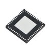
Part Details for MAX5961ETM+ by Maxim Integrated Products
Results Overview of MAX5961ETM+ by Maxim Integrated Products
- Distributor Offerings: (2 listings)
- Number of FFF Equivalents: (0 replacements)
- CAD Models: (Request Part)
- Number of Functional Equivalents: (0 options)
- Part Data Attributes: (Available)
- Reference Designs: (Not Available)
Tip: Data for a part may vary between manufacturers. You can filter for manufacturers on the top of the page next to the part image and part number.
MAX5961ETM+ Information
MAX5961ETM+ by Maxim Integrated Products is a Power Management Circuit.
Power Management Circuits are under the broader part category of Power Circuits.
A power circuit delivers electricity in order to operate a load for an electronic device. Power circuits include transformers, generators and switches. Read more about Power Circuits on our Power Circuits part category page.
Price & Stock for MAX5961ETM+
| Part # | Distributor | Description | Stock | Price | Buy | |
|---|---|---|---|---|---|---|
|
DISTI #
MAX5961ETM+-ND
|
DigiKey | IC HOT SWAP CTRLR PCI EXP 48TQFN Min Qty: 129 Lead time: 10 Weeks Container: Tube | Temporarily Out of Stock |
|
$11.0800 | Buy Now |
|
|
Quest Components | 4-CHANNEL POWER SUPPLY SUPPORT CKT, QCC48 | 12421 |
|
$5.2500 / $10.5000 | Buy Now |
Part Details for MAX5961ETM+
MAX5961ETM+ CAD Models
MAX5961ETM+ Part Data Attributes
|
|
MAX5961ETM+
Maxim Integrated Products
Buy Now
Datasheet
|
Compare Parts:
MAX5961ETM+
Maxim Integrated Products
Power Supply Support Circuit, Adjustable, 4 Channel, BICMOS, 7 X 7 MM, ROHS COMPLIANT, MO-220, TQFN-48
|
| Pbfree Code | No | |
| Rohs Code | Yes | |
| Part Life Cycle Code | Transferred | |
| Ihs Manufacturer | MAXIM INTEGRATED PRODUCTS INC | |
| Part Package Code | QFN | |
| Package Description | 7 X 7 MM, ROHS COMPLIANT, MO-220, TQFN-48 | |
| Pin Count | 48 | |
| Reach Compliance Code | compliant | |
| ECCN Code | EAR99 | |
| HTS Code | 8542.31.00.01 | |
| Adjustable Threshold | YES | |
| Analog IC - Other Type | POWER SUPPLY SUPPORT CIRCUIT | |
| JESD-30 Code | S-XQCC-N48 | |
| JESD-609 Code | e3 | |
| Length | 7 mm | |
| Moisture Sensitivity Level | 1 | |
| Number of Channels | 4 | |
| Number of Functions | 1 | |
| Number of Terminals | 48 | |
| Operating Temperature-Max | 85 °C | |
| Operating Temperature-Min | -40 °C | |
| Package Body Material | UNSPECIFIED | |
| Package Code | HVQCCN | |
| Package Shape | SQUARE | |
| Package Style | CHIP CARRIER, HEAT SINK/SLUG, VERY THIN PROFILE | |
| Peak Reflow Temperature (Cel) | 260 | |
| Qualification Status | Not Qualified | |
| Seated Height-Max | 0.9 mm | |
| Supply Voltage-Max (Vsup) | 16 V | |
| Supply Voltage-Min (Vsup) | 2.7 V | |
| Supply Voltage-Nom (Vsup) | 3.3 V | |
| Surface Mount | YES | |
| Technology | BICMOS | |
| Temperature Grade | INDUSTRIAL | |
| Terminal Finish | MATTE TIN | |
| Terminal Form | NO LEAD | |
| Terminal Pitch | 0.5 mm | |
| Terminal Position | QUAD | |
| Time@Peak Reflow Temperature-Max (s) | 30 | |
| Width | 7 mm |
MAX5961ETM+ Frequently Asked Questions (FAQ)
-
A good PCB layout for the MAX5961ETM+ involves keeping the input and output traces short and separate, using a solid ground plane, and placing the input and output capacitors close to the device. Additionally, it's recommended to use a 4-layer PCB with a dedicated power plane and a dedicated ground plane.
-
To ensure proper power-up and power-down of the MAX5961ETM+, it's recommended to follow a controlled power-up sequence, where the input voltage is applied before the enable pin is asserted. During power-down, the enable pin should be de-asserted before the input voltage is removed.
-
The MAX5961ETM+ has a thermal shutdown feature that protects the device from overheating. To ensure reliable operation, it's recommended to provide adequate heat sinking, such as a thermal pad or a heat sink, and to keep the device away from other heat sources.
-
To troubleshoot issues with the MAX5961ETM+, start by verifying the input voltage and enable pin signals. Check for proper power-up and power-down sequencing, and ensure that the device is properly soldered and connected. Use an oscilloscope to verify the output voltage and current.
-
To minimize EMI and EMC issues with the MAX5961ETM+, use a shielded enclosure, keep the device away from other noise sources, and use a common-mode choke or ferrite bead on the input and output lines. Additionally, ensure that the PCB layout is designed to minimize radiation and susceptibility.
