-
Part Symbol
-
Footprint
-
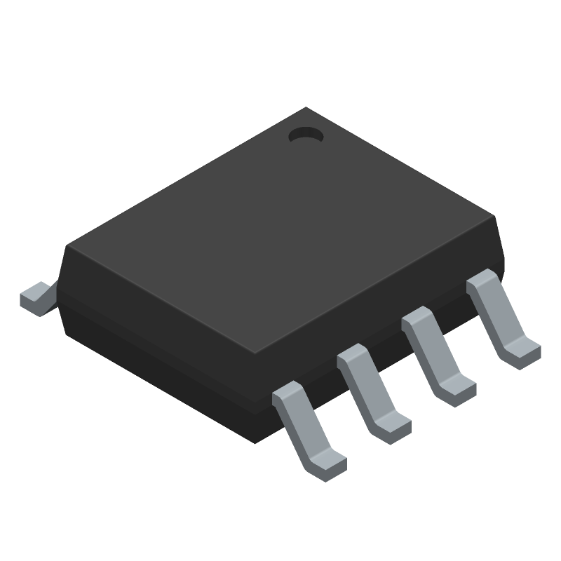
3D Model
Available Download Formats
By downloading CAD models, you agree to our Terms & Conditions and Privacy Policy
3.3V Powered, 10Mbps and Slew-Rate Limited, True RS-485/RS-422 Transceivers, 8-SOIC_N-150_MIL, 8 Pins, 0 to 70C
Tip: Data for a part may vary between manufacturers. You can filter for manufacturers on the top of the page next to the part image and part number.
MAX3488CSA+ by Analog Devices Inc is a Line Driver or Receiver.
Line Driver or Receivers are under the broader part category of Drivers And Interfaces.
A driver controls the current or voltage delivered to components like LCDs or motors, while an interface component connects systems for data transfer and control. Read more about Drivers And Interfaces on our Drivers And Interfaces part category page.
| Part # | Distributor | Description | Stock | Price | Buy | |
|---|---|---|---|---|---|---|
|
DISTI #
700-MAX3488CSA
|
Mouser Electronics | RS-422/RS-485 Interface IC 3.3V Powered, 10Mbps and Slew-Rate Limit RoHS: Compliant | 1145 |
|
$3.6400 / $6.6500 | Buy Now |
|
|
Analog Devices Inc | 3.3V Powered, 10Mbps and Slew- Package Multiple: 1 | 3943 |
|
$2.8100 / $8.2200 | Buy Now |
By downloading CAD models, you agree to our Terms & Conditions and Privacy Policy
|
|
MAX3488CSA+
Analog Devices Inc
Buy Now
Datasheet
|
Compare Parts:
MAX3488CSA+
Analog Devices Inc
3.3V Powered, 10Mbps and Slew-Rate Limited, True RS-485/RS-422 Transceivers, 8-SOIC_N-150_MIL, 8 Pins, 0 to 70C
|
| Rohs Code | Yes | |
| Part Life Cycle Code | Active | |
| Ihs Manufacturer | ANALOG DEVICES INC | |
| Part Package Code | 8-SOIC_N-150_MIL | |
| Package Description | 0.150 INCH, SO-8 | |
| Pin Count | 8 | |
| Manufacturer Package Code | 8-SOIC_N-150_MIL | |
| Reach Compliance Code | compliant | |
| Date Of Intro | 1994-12-01 | |
| Samacsys Manufacturer | Analog Devices | |
| Differential Output | YES | |
| Driver Number of Bits | 1 | |
| High Level Input Current-Max | 0.000002 A | |
| Input Characteristics | DIFFERENTIAL SCHMITT TRIGGER | |
| Interface IC Type | LINE TRANSCEIVER | |
| Interface Standard | EIA-422; EIA-485 | |
| JESD-30 Code | R-PDSO-G8 | |
| JESD-609 Code | e3 | |
| Length | 4.9 mm | |
| Moisture Sensitivity Level | 1 | |
| Number of Functions | 1 | |
| Number of Terminals | 8 | |
| Operating Temperature-Max | 70 °C | |
| Operating Temperature-Min | ||
| Out Swing-Min | 2 V | |
| Output Characteristics | TOTEM-POLE | |
| Output Low Current-Max | 0.0025 A | |
| Output Polarity | COMPLEMENTARY | |
| Package Body Material | PLASTIC/EPOXY | |
| Package Code | SOP | |
| Package Equivalence Code | SOP8,.25 | |
| Package Shape | RECTANGULAR | |
| Package Style | SMALL OUTLINE | |
| Peak Reflow Temperature (Cel) | 260 | |
| Qualification Status | Not Qualified | |
| Receive Delay-Max | 120 ns | |
| Receiver Number of Bits | 1 | |
| Seated Height-Max | 1.75 mm | |
| Supply Current-Max | 2.2 mA | |
| Supply Voltage-Max | 3.6 V | |
| Supply Voltage-Min | 3 V | |
| Supply Voltage-Nom | 3.3 V | |
| Surface Mount | YES | |
| Technology | CMOS | |
| Temperature Grade | COMMERCIAL | |
| Terminal Finish | Matte Tin (Sn) | |
| Terminal Form | GULL WING | |
| Terminal Pitch | 1.27 mm | |
| Terminal Position | DUAL | |
| Time@Peak Reflow Temperature-Max (s) | 30 | |
| Transmit Delay-Max | 1400 ns | |
| Width | 3.9 mm |
This table gives cross-reference parts and alternative options found for MAX3488CSA+. The Form Fit Function (FFF) tab will give you the options that are more likely to serve as direct pin-to-pin alternates or drop-in parts. The Functional Equivalents tab will give you options that are likely to match the same function of MAX3488CSA+, but it may not fit your design. Always verify details of parts you are evaluating, as these parts are offered as suggestions for what you are looking for and are not guaranteed.
| Part Number | Manufacturer | Composite Price | Description | Compare |
|---|---|---|---|---|
| MAX3488ESA-T | Maxim Integrated Products | Check for Price | Line Transceiver, 1 Func, 1 Driver, 1 Rcvr, CMOS, PDSO8, 0.150 INCH, SO-8 | MAX3488CSA+ vs MAX3488ESA-T |
| MAX3488CSA+T | Analog Devices Inc | Check for Price | 3.3V Powered, 10Mbps and Slew-Rate Limited, True RS-485/RS-422 Transceivers, 8-SOIC_N-150_MIL, 8 Pins, 0 to 70C | MAX3488CSA+ vs MAX3488CSA+T |
| MAX3488CSA-T | Maxim Integrated Products | Check for Price | Line Transceiver, 1 Func, 1 Driver, 1 Rcvr, CMOS, PDSO8, 0.150 INCH, SO-8 | MAX3488CSA+ vs MAX3488CSA-T |
The recommended layout and routing for the MAX3488CSA+ involves keeping the analog and digital grounds separate, using a solid ground plane, and minimizing the length of the traces between the device and the capacitors. It's also important to keep the device away from high-frequency noise sources and to use a low-ESR capacitor for the VCC bypass.
To ensure reliable operation of the MAX3488CSA+ in high-temperature environments, it's essential to follow proper thermal management practices, such as providing adequate heat sinking, using a thermally conductive PCB material, and keeping the device away from heat sources. Additionally, the device should be operated within its specified temperature range, and the power dissipation should be kept within the recommended limits.
Using a lower value for the VCC bypass capacitor can lead to increased noise and reduced stability, while using a higher value can increase the startup time and reduce the overall efficiency of the device. The recommended value for the VCC bypass capacitor is 0.1uF to 1uF, and it's essential to choose a capacitor with a low equivalent series resistance (ESR) to minimize the impact on the device's performance.
To troubleshoot issues with the MAX3488CSA+, start by verifying the power supply voltage and ensuring that it's within the recommended range. Check the device's output voltage and current, and verify that the input signals are within the specified range. Use an oscilloscope to check for noise and oscillations, and consult the datasheet and application notes for guidance on troubleshooting specific issues.
Using the MAX3488CSA+ in a non-standard application can lead to reduced performance, reliability, and efficiency. It's essential to carefully review the datasheet and application notes to ensure that the device is used within its specified operating conditions and that the application meets the device's requirements. Additionally, it may be necessary to perform additional testing and validation to ensure that the device operates reliably in the non-standard application.