-
Part Symbol
-
Footprint
-
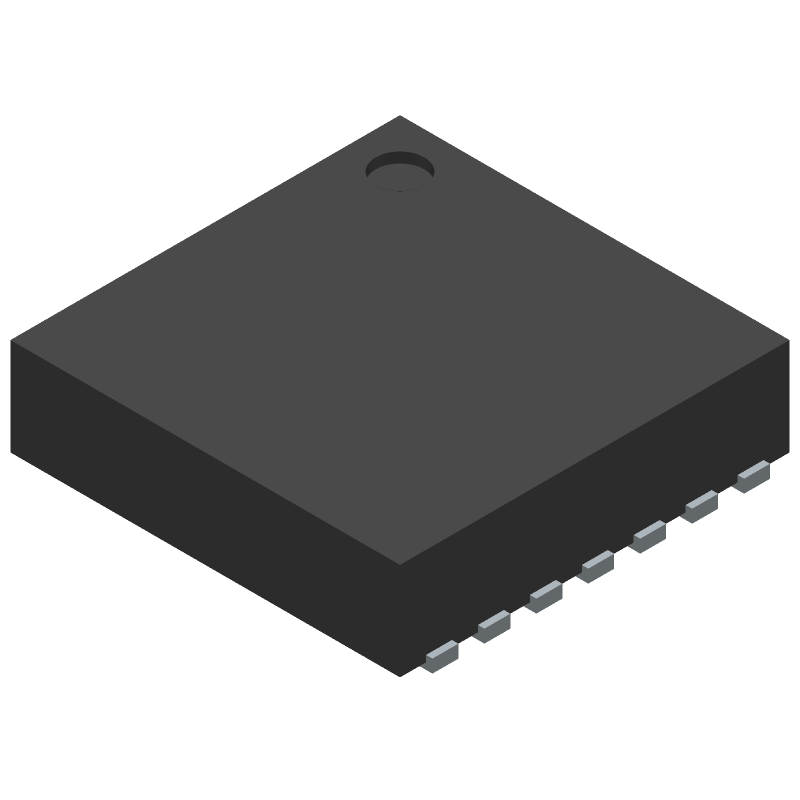
3D Model
Available Download Formats
By downloading CAD models, you agree to our Terms & Conditions and Privacy Policy
Dual Electroluminescent Lamp Driver, 14-LFCSP-3X3X0.75, 14 Pins, -40 to 85C
Tip: Data for a part may vary between manufacturers. You can filter for manufacturers on the top of the page next to the part image and part number.
MAX14514ETD+T by Analog Devices Inc is a Display Driver.
Display Drivers are under the broader part category of Drivers And Interfaces.
A driver controls the current or voltage delivered to components like LCDs or motors, while an interface component connects systems for data transfer and control. Read more about Drivers And Interfaces on our Drivers And Interfaces part category page.
| Part # | Distributor | Description | Stock | Price | Buy | |
|---|---|---|---|---|---|---|
|
DISTI #
700-MAX14514ETD+T
|
Mouser Electronics | Display Drivers & Controllers Dual Electroluminescent Lamp Driver RoHS: Compliant | 0 |
|
$5.3500 | Order Now |
|
|
Analog Devices Inc | Dual Electroluminescent Lamp D Min Qty: 2500 Package Multiple: 1 | 0 |
|
$4.3100 / $5.3875 | Buy Now |
|
|
Vyrian | Peripheral ICs | 218 |
|
RFQ |
By downloading CAD models, you agree to our Terms & Conditions and Privacy Policy
|
|
MAX14514ETD+T
Analog Devices Inc
Buy Now
Datasheet
|
Compare Parts:
MAX14514ETD+T
Analog Devices Inc
Dual Electroluminescent Lamp Driver, 14-LFCSP-3X3X0.75, 14 Pins, -40 to 85C
|
| Rohs Code | Yes | |
| Part Life Cycle Code | Active | |
| Ihs Manufacturer | ANALOG DEVICES INC | |
| Part Package Code | 14-LFCSP-3X3X0.75 | |
| Pin Count | 14 | |
| Manufacturer Package Code | 14-LFCSP-3X3X0.75 | |
| Reach Compliance Code | compliant | |
| Date Of Intro | 2010-04-23 | |
| Samacsys Manufacturer | Analog Devices | |
| Interface IC Type | EL DISPLAY DRIVER | |
| JESD-609 Code | e3 | |
| Moisture Sensitivity Level | 1 | |
| Peak Reflow Temperature (Cel) | 260 | |
| Terminal Finish | Matte Tin (Sn) | |
| Time@Peak Reflow Temperature-Max (s) | 30 |
This table gives cross-reference parts and alternative options found for MAX14514ETD+T. The Form Fit Function (FFF) tab will give you the options that are more likely to serve as direct pin-to-pin alternates or drop-in parts. The Functional Equivalents tab will give you options that are likely to match the same function of MAX14514ETD+T, but it may not fit your design. Always verify details of parts you are evaluating, as these parts are offered as suggestions for what you are looking for and are not guaranteed.
| Part Number | Manufacturer | Composite Price | Description | Compare |
|---|---|---|---|---|
| HV860K7-G | Microchip Technology Inc | $1.4350 | EL DISPLAY DRIVER, QCC12 | MAX14514ETD+T vs HV860K7-G |
| MIC4833YML-TR | Microchip Technology Inc | $2.4550 | EL DISPLAY DRIVER, DSO12 | MAX14514ETD+T vs MIC4833YML-TR |
| MAX14514ETD+T | Maxim Integrated Products | Check for Price | EL Driver, | MAX14514ETD+T vs MAX14514ETD+T |
| MIC4833YML | Microchip Technology Inc | Check for Price | EL DISPLAY DRIVER, DSO12 | MAX14514ETD+T vs MIC4833YML |
A good PCB layout for the MAX14514ETD+T involves keeping the analog and digital grounds separate, using a solid ground plane, and placing the device close to the power supply. Additionally, it's recommended to use a 4-layer PCB with a dedicated layer for the analog signals to minimize noise and interference.
The MAX14514ETD+T has a thermal pad on the bottom of the package, which should be connected to a thermal plane on the PCB to dissipate heat. A thermal interface material (TIM) can be used to improve heat transfer between the device and the thermal plane. Additionally, ensuring good airflow around the device and using a heat sink if necessary can help to keep the device within its operating temperature range.
The recommended input voltage range for the MAX14514ETD+T is 2.7V to 5.5V. Operating the device outside of this range may affect its performance and reliability.
The MAX14514ETD+T can be configured for I2C or SPI communication by setting the appropriate pins high or low. For I2C mode, the SCL pin should be connected to a clock signal and the SDA pin should be connected to a data signal. For SPI mode, the SCK pin should be connected to a clock signal, the MOSI pin should be connected to a data input signal, and the MISO pin should be connected to a data output signal. The specific pin connections and configuration will depend on the application and the microcontroller being used.
The maximum data transfer rate of the MAX14514ETD+T depends on the communication mode being used. In I2C mode, the maximum data transfer rate is 400 kHz. In SPI mode, the maximum data transfer rate is 20 MHz.