-
Part Symbol
-
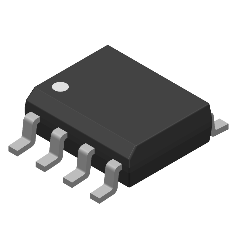
Footprint
-
3D Model
Available Download Formats
By downloading CAD models, you agree to our Terms & Conditions and Privacy Policy
+5.0V, ±15kV ESD-Protected, Fail-Safe, Hot-Swap, RS-485/RS-422 Transceiver, 8-SOIC_N-150_MIL, 8 Pins, -40 to 85C
Tip: Data for a part may vary between manufacturers. You can filter for manufacturers on the top of the page next to the part image and part number.
MAX13085EESA+ by Analog Devices Inc is a Line Driver or Receiver.
Line Driver or Receivers are under the broader part category of Drivers And Interfaces.
A driver controls the current or voltage delivered to components like LCDs or motors, while an interface component connects systems for data transfer and control. Read more about Drivers And Interfaces on our Drivers And Interfaces part category page.
| Part # | Distributor | Description | Stock | Price | Buy | |
|---|---|---|---|---|---|---|
|
DISTI #
700-MAX13085EESA
|
Mouser Electronics | RS-422/RS-485 Interface IC +5.0V, 15kV ESD-Protected, Fail-Safe, Hot-Swap, RS-485/RS-422 Transceiver RoHS: Compliant | 806 |
|
$2.9800 / $5.5100 | Buy Now |
|
|
Analog Devices Inc | +5.0V, ±15kV ESD-Protected, Fa Package Multiple: 1 | 16355 |
|
$3.0845 / $5.5100 | Buy Now |
By downloading CAD models, you agree to our Terms & Conditions and Privacy Policy
|
|
MAX13085EESA+
Analog Devices Inc
Buy Now
Datasheet
|
Compare Parts:
MAX13085EESA+
Analog Devices Inc
+5.0V, ±15kV ESD-Protected, Fail-Safe, Hot-Swap, RS-485/RS-422 Transceiver, 8-SOIC_N-150_MIL, 8 Pins, -40 to 85C
|
| Rohs Code | Yes | |
| Part Life Cycle Code | Active | |
| Ihs Manufacturer | ANALOG DEVICES INC | |
| Part Package Code | 8-SOIC_N-150_MIL | |
| Package Description | 0.150 INCH, MS-012AA, SOIC-8 | |
| Pin Count | 8 | |
| Manufacturer Package Code | 8-SOIC_N-150_MIL | |
| Reach Compliance Code | compliant | |
| Date Of Intro | 2012-03-08 | |
| Samacsys Manufacturer | Analog Devices | |
| Differential Output | YES | |
| Driver Number of Bits | 1 | |
| Input Characteristics | DIFFERENTIAL SCHMITT TRIGGER | |
| Interface IC Type | LINE TRANSCEIVER | |
| Interface Standard | EIA-422; EIA-485 | |
| JESD-30 Code | R-PDSO-G8 | |
| JESD-609 Code | e3 | |
| Length | 4.9 mm | |
| Moisture Sensitivity Level | 1 | |
| Number of Functions | 1 | |
| Number of Terminals | 8 | |
| Operating Temperature-Max | 85 °C | |
| Operating Temperature-Min | -40 °C | |
| Out Swing-Min | 2 V | |
| Output Low Current-Max | 0.001 A | |
| Package Body Material | PLASTIC/EPOXY | |
| Package Code | SOP | |
| Package Equivalence Code | SOP8,.25 | |
| Package Shape | RECTANGULAR | |
| Package Style | SMALL OUTLINE | |
| Peak Reflow Temperature (Cel) | 260 | |
| Qualification Status | Not Qualified | |
| Receive Delay-Max | 200 ns | |
| Receiver Number of Bits | 1 | |
| Seated Height-Max | 1.75 mm | |
| Supply Current-Max | 1.8 mA | |
| Supply Voltage-Max | 5.5 V | |
| Supply Voltage-Min | 4.5 V | |
| Supply Voltage-Nom | 5 V | |
| Surface Mount | YES | |
| Technology | BICMOS | |
| Temperature Grade | INDUSTRIAL | |
| Terminal Finish | Matte Tin (Sn) | |
| Terminal Form | GULL WING | |
| Terminal Pitch | 1.27 mm | |
| Terminal Position | DUAL | |
| Time@Peak Reflow Temperature-Max (s) | 30 | |
| Transmit Delay-Max | 1000 ns | |
| Width | 3.9 mm |
This table gives cross-reference parts and alternative options found for MAX13085EESA+. The Form Fit Function (FFF) tab will give you the options that are more likely to serve as direct pin-to-pin alternates or drop-in parts. The Functional Equivalents tab will give you options that are likely to match the same function of MAX13085EESA+, but it may not fit your design. Always verify details of parts you are evaluating, as these parts are offered as suggestions for what you are looking for and are not guaranteed.
| Part Number | Manufacturer | Composite Price | Description | Compare |
|---|---|---|---|---|
| MAX13085ECSA | Rochester Electronics LLC | Check for Price | LINE TRANSCEIVER, PDSO8, 0.150 INCH, MS-012AA, SOIC-8 | MAX13085EESA+ vs MAX13085ECSA |
The recommended PCB layout for the MAX13085EESA+ is to use a 4-layer board with a solid ground plane, and to keep the analog and digital signals separate. Additionally, it's recommended to use a low-ESR capacitor for the VCC bypass and to place it as close as possible to the VCC pin.
To ensure proper power-up and power-down of the MAX13085EESA+, it's recommended to follow a specific power-up sequence. First, power up the VCC supply, then the VDD supply, and finally the EN pin. During power-down, reverse the sequence. Additionally, make sure to add a power-on reset circuit to ensure the device is properly reset during power-up.
The maximum cable length supported by the MAX13085EESA+ depends on the specific application and the type of cable used. However, as a general guideline, the device can support cable lengths up to 100 meters for RS-485 and up to 10 meters for RS-232. It's recommended to use a cable with a characteristic impedance of 120 ohms for RS-485 and 1 kohm for RS-232.
To troubleshoot communication issues with the MAX13085EESA+, first check the power supply and ensure it's within the recommended range. Then, verify the correct configuration of the device, including the baud rate, data bits, and parity. Use a logic analyzer or oscilloscope to check the signal integrity and timing. Finally, check for any noise or interference on the communication lines.
Yes, the MAX13085EESA+ is compatible with both 3.3V and 5V logic levels. The device has a wide supply voltage range of 3.0V to 5.5V, and its digital inputs are 5V-tolerant. However, it's recommended to use a voltage level translator if the device is connected to a 5V system and the digital inputs are driven by a 3.3V system.