-
Part Symbol
-
Footprint
-
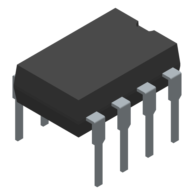
3D Model
Available Download Formats
By downloading CAD models, you agree to our Terms & Conditions and Privacy Policy
Differential Driver and Receiver Pair
Tip: Data for a part may vary between manufacturers. You can filter for manufacturers on the top of the page next to the part image and part number.
LTC490IN8#PBF by Analog Devices Inc is a Line Driver or Receiver.
Line Driver or Receivers are under the broader part category of Drivers And Interfaces.
A driver controls the current or voltage delivered to components like LCDs or motors, while an interface component connects systems for data transfer and control. Read more about Drivers And Interfaces on our Drivers And Interfaces part category page.
| Part # | Distributor | Description | Stock | Price | Buy | |
|---|---|---|---|---|---|---|
|
DISTI #
51AK7274
|
Newark | Rs422/Rs485 Diff Transceiver, 85Deg C, Ic Type:Rs422/Rs485 Transceiver, No. Of Receivers:1Receivers, No. Of Transmitters:1, Communication Mode:Full Duplex, Data Rate Max:2.5Mbps, Supply Voltage Min:4.75V, Supply Voltage Max:5.25V Rohs Compliant: Yes |Analog Devices LTC490IN8#PBF RoHS: Compliant Min Qty: 1 Package Multiple: 1 Date Code: 1 Container: Bulk | 241 |
|
$4.7400 / $10.2500 | Buy Now |
|
DISTI #
LTC490IN8#PBF-ND
|
DigiKey | IC TRANSCEIVER FULL 1/1 8PDIP Min Qty: 1 Lead time: 10 Weeks Container: Tube |
460 In Stock |
|
$4.7375 / $10.2500 | Buy Now |
|
DISTI #
584-LTC490IN8#PBF
|
Mouser Electronics | RS-422/RS-485 Interface IC Diff Drvr & Rcv Pair RoHS: Compliant | 20 |
|
$4.9200 / $8.7200 | Buy Now |
|
|
Analog Devices Inc | Diff Drvr & Rcv Pair Package Multiple: 50 | 142 |
|
$3.7900 / $10.2500 | Buy Now |
|
|
Rochester Electronics | LTC490 - Low Power RS485 Tx/Rx RoHS: Compliant Status: Active Min Qty: 1 | 15 |
|
$3.9800 / $4.9700 | Buy Now |
|
DISTI #
LTC490IN8#PBF
|
Richardson RFPD | INTERFACE - TRANSCEIVER RoHS: Compliant Min Qty: 100 | 0 |
|
$4.9000 / $5.3700 | Buy Now |
By downloading CAD models, you agree to our Terms & Conditions and Privacy Policy
|
|
LTC490IN8#PBF
Analog Devices Inc
Buy Now
Datasheet
|
Compare Parts:
LTC490IN8#PBF
Analog Devices Inc
Differential Driver and Receiver Pair
|
| Pbfree Code | No | |
| Rohs Code | Yes | |
| Part Life Cycle Code | Active | |
| Ihs Manufacturer | ANALOG DEVICES INC | |
| Package Description | PLASTIC, DIP-8 | |
| Pin Count | 8 | |
| Manufacturer Package Code | 05-08-1510 (N8) | |
| Reach Compliance Code | compliant | |
| Samacsys Manufacturer | Analog Devices | |
| Differential Output | YES | |
| Driver Number of Bits | 1 | |
| Input Characteristics | DIFFERENTIAL SCHMITT TRIGGER | |
| Interface IC Type | LINE TRANSCEIVER | |
| Interface Standard | EIA-422; EIA-485 | |
| JESD-30 Code | R-PDIP-T8 | |
| JESD-609 Code | e3 | |
| Length | 10.16 mm | |
| Moisture Sensitivity Level | 1 | |
| Number of Functions | 1 | |
| Number of Terminals | 8 | |
| Operating Temperature-Max | 85 °C | |
| Operating Temperature-Min | -40 °C | |
| Output Characteristics | TOTEM-POLE | |
| Output Polarity | COMPLEMENTARY | |
| Package Body Material | PLASTIC/EPOXY | |
| Package Code | DIP | |
| Package Shape | RECTANGULAR | |
| Package Style | IN-LINE | |
| Peak Reflow Temperature (Cel) | 260 | |
| Qualification Status | Not Qualified | |
| Receive Delay-Max | 150 ns | |
| Receiver Number of Bits | 1 | |
| Seated Height-Max | 3.937 mm | |
| Supply Voltage-Max | 5.25 V | |
| Supply Voltage-Min | 4.75 V | |
| Supply Voltage-Nom | 5 V | |
| Surface Mount | NO | |
| Technology | CMOS | |
| Temperature Grade | INDUSTRIAL | |
| Terminal Finish | Matte Tin (Sn) | |
| Terminal Form | THROUGH-HOLE | |
| Terminal Pitch | 2.54 mm | |
| Terminal Position | DUAL | |
| Time@Peak Reflow Temperature-Max (s) | 30 | |
| Transmit Delay-Max | 50 ns | |
| Width | 7.62 mm |
This table gives cross-reference parts and alternative options found for LTC490IN8#PBF. The Form Fit Function (FFF) tab will give you the options that are more likely to serve as direct pin-to-pin alternates or drop-in parts. The Functional Equivalents tab will give you options that are likely to match the same function of LTC490IN8#PBF, but it may not fit your design. Always verify details of parts you are evaluating, as these parts are offered as suggestions for what you are looking for and are not guaranteed.
| Part Number | Manufacturer | Composite Price | Description | Compare |
|---|---|---|---|---|
| SN65LBC179P | Texas Instruments | $1.9230 | Low-Power Differential Line Driver And Receiver Pair 8-PDIP -40 to 85 | LTC490IN8#PBF vs SN65LBC179P |
| LTC490IN8 | Linear Technology | Check for Price | LTC490 - Differential Driver and Receiver Pair; Package: PDIP; Pins: 8; Temperature Range: -40°C to 85°C | LTC490IN8#PBF vs LTC490IN8 |
| LTC490IN8 | Analog Devices Inc | Check for Price | Line Transceiver, 1 Func, 1 Driver, 1 Rcvr, CMOS, PDIP8 | LTC490IN8#PBF vs LTC490IN8 |
A good PCB layout for the LTC490IN8 involves keeping the analog and digital grounds separate, using a solid ground plane, and minimizing noise coupling between the input and output stages. A 4-layer PCB with a dedicated analog ground plane is recommended.
To ensure accurate temperature measurement, it's essential to calibrate the device, use a high-accuracy voltage reference, and minimize thermal gradients on the PCB. Additionally, the device should be mounted in a way that minimizes thermal coupling to the surrounding environment.
The maximum cable length for the remote sense lines depends on the specific application and the noise environment. As a general rule, keep the sense lines as short as possible (less than 10 inches) and use twisted pair cables to minimize noise pickup. If longer cables are necessary, use shielded cables and consider adding noise filtering or amplification.
Yes, the LTC490IN8 can be used with a switching power supply, but it's essential to ensure that the power supply's output noise is within the device's specified noise tolerance. Additionally, consider adding noise filtering or decoupling capacitors to minimize the impact of power supply noise on the device's performance.
To troubleshoot common issues with the LTC490IN8, start by checking the PCB layout and ensuring that it meets the recommended layout guidelines. Verify that the input and output voltages are within the specified ranges, and check for noise or oscillations on the input and output lines. Use an oscilloscope to visualize the waveforms and identify any anomalies. Consult the datasheet and application notes for specific troubleshooting guidance.