-
Part Symbol
-
Footprint
-
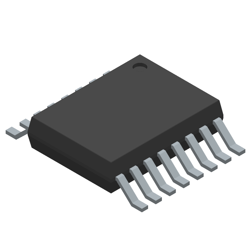
3D Model
Available Download Formats
By downloading CAD models, you agree to our Terms & Conditions and Privacy Policy
Two-Supply Diode-OR Current Balancing Controller
Tip: Data for a part may vary between manufacturers. You can filter for manufacturers on the top of the page next to the part image and part number.
LTC4370CMS#TRPBF by Analog Devices Inc is a Power Management Circuit.
Power Management Circuits are under the broader part category of Power Circuits.
A power circuit delivers electricity in order to operate a load for an electronic device. Power circuits include transformers, generators and switches. Read more about Power Circuits on our Power Circuits part category page.
| Part # | Distributor | Description | Stock | Price | Buy | |
|---|---|---|---|---|---|---|
|
DISTI #
505-LTC4370CMS#TRPBFTR-ND
|
DigiKey | IC OR CTRLR N-CH 2CH 16MSOP Min Qty: 2500 Lead time: 10 Weeks Container: Tape & Reel (TR) | Temporarily Out of Stock |
|
$7.3750 | Buy Now |
|
DISTI #
584-LTC4370CMS#TRPBF
|
Mouser Electronics | Power Management Specialized - PMIC Two-S Diode-OR C Balancing Cntr RoHS: Compliant | 0 |
|
$7.3700 | Order Now |
|
|
Analog Devices Inc | Two-S Diode-OR C Balancing Cnt Min Qty: 2500 Package Multiple: 2500 | 0 |
|
$5.9000 / $15.1900 | Buy Now |
|
DISTI #
LTC4370CMSTRPBF
|
Richardson RFPD | POWER MANAGEMENT IC RoHS: Compliant Min Qty: 2500 | 0 |
|
$7.6200 / $7.9200 | Buy Now |
By downloading CAD models, you agree to our Terms & Conditions and Privacy Policy
|
|
LTC4370CMS#TRPBF
Analog Devices Inc
Buy Now
Datasheet
|
Compare Parts:
LTC4370CMS#TRPBF
Analog Devices Inc
Two-Supply Diode-OR Current Balancing Controller
|
| Pbfree Code | No | |
| Rohs Code | Yes | |
| Part Life Cycle Code | Active | |
| Ihs Manufacturer | ANALOG DEVICES INC | |
| Package Description | LEAD FREE, PLASTIC, MSOP-16 | |
| Pin Count | 16 | |
| Manufacturer Package Code | 05-08-1669 | |
| Reach Compliance Code | compliant | |
| Samacsys Manufacturer | Analog Devices | |
| Adjustable Threshold | YES | |
| Analog IC - Other Type | POWER SUPPLY SUPPORT CIRCUIT | |
| JESD-30 Code | R-PDSO-G16 | |
| JESD-609 Code | e3 | |
| Length | 4.039 mm | |
| Moisture Sensitivity Level | 1 | |
| Number of Channels | 1 | |
| Number of Functions | 1 | |
| Number of Terminals | 16 | |
| Operating Temperature-Max | 70 °C | |
| Operating Temperature-Min | ||
| Package Body Material | PLASTIC/EPOXY | |
| Package Code | TSSOP | |
| Package Shape | RECTANGULAR | |
| Package Style | SMALL OUTLINE, THIN PROFILE, SHRINK PITCH | |
| Peak Reflow Temperature (Cel) | 260 | |
| Seated Height-Max | 1.1 mm | |
| Supply Voltage-Max (Vsup) | 18 V | |
| Supply Voltage-Min (Vsup) | 2.9 V | |
| Supply Voltage-Nom (Vsup) | 12 V | |
| Surface Mount | YES | |
| Technology | CMOS | |
| Temperature Grade | COMMERCIAL | |
| Terminal Finish | Matte Tin (Sn) | |
| Terminal Form | GULL WING | |
| Terminal Pitch | 0.5 mm | |
| Terminal Position | DUAL | |
| Time@Peak Reflow Temperature-Max (s) | 30 | |
| Width | 3 mm |
This table gives cross-reference parts and alternative options found for LTC4370CMS#TRPBF. The Form Fit Function (FFF) tab will give you the options that are more likely to serve as direct pin-to-pin alternates or drop-in parts. The Functional Equivalents tab will give you options that are likely to match the same function of LTC4370CMS#TRPBF, but it may not fit your design. Always verify details of parts you are evaluating, as these parts are offered as suggestions for what you are looking for and are not guaranteed.
| Part Number | Manufacturer | Composite Price | Description | Compare |
|---|---|---|---|---|
| LTC3765HMSE#TRPBF | Analog Devices Inc | Check for Price | Active Clamp Forward Controller and Gate Driver | LTC4370CMS#TRPBF vs LTC3765HMSE#TRPBF |
| LTC4370IMS#TRPBF | Linear Technology | Check for Price | LTC4370 - Two-Supply Diode-OR Current Balancing Controller; Package: MSOP; Pins: 16; Temperature Range: -40°C to 85°C | LTC4370CMS#TRPBF vs LTC4370IMS#TRPBF |
| LTC4364CMS-1#TRPBF | Linear Technology | Check for Price | LTC4364 - Surge Stopper with Ideal Diode; Package: MSOP; Pins: 16; Temperature Range: 0°C to 70°C | LTC4370CMS#TRPBF vs LTC4364CMS-1#TRPBF |
| LTC3765IMSE#PBF | Analog Devices Inc | Check for Price | Active Clamp Forward Controller and Gate Driver | LTC4370CMS#TRPBF vs LTC3765IMSE#PBF |
| LTC4364CMS-1#PBF | Linear Technology | Check for Price | LTC4364 - Surge Stopper with Ideal Diode; Package: MSOP; Pins: 16; Temperature Range: 0°C to 70°C | LTC4370CMS#TRPBF vs LTC4364CMS-1#PBF |
| LTC2965CMS#PBF | Linear Technology | Check for Price | LTC2965 - 100V Micropower Single Voltage Monitor; Package: MSOP; Pins: 16; Temperature Range: 0°C to 70°C | LTC4370CMS#TRPBF vs LTC2965CMS#PBF |
| LTC4364IMS-1#TRPBF | Analog Devices Inc | Check for Price | Surge Stopper with Ideal Diode | LTC4370CMS#TRPBF vs LTC4364IMS-1#TRPBF |
| LTC4370IMS#TRPBF | Analog Devices Inc | Check for Price | Two-Supply Diode-OR Current Balancing Controller | LTC4370CMS#TRPBF vs LTC4370IMS#TRPBF |
A good PCB layout for the LTC4370 involves keeping the input and output capacitors close to the device, using a solid ground plane, and minimizing trace lengths and widths to reduce parasitic inductance and capacitance. A 4-layer PCB with a dedicated power plane and a solid ground plane is recommended.
The input capacitor should be a low-ESR ceramic capacitor with a value of at least 10uF, while the output capacitor should be a low-ESR ceramic or tantalum capacitor with a value of at least 22uF. The capacitor selection should also consider the voltage rating, ripple current rating, and temperature rating.
The LTC4370 is rated for operation from -40°C to 125°C, but the maximum ambient temperature range depends on the specific application and the device's power dissipation. A thermal analysis should be performed to ensure the device operates within its thermal limits.
The output voltage of the LTC4370 can be set using the FB pin and an external resistor divider network. The resistor values can be calculated using the formula provided in the datasheet, and the output voltage can be adjusted from 0.8V to 5V.
The LTC4370 can operate with input voltages from 2.5V to 5.5V, but the maximum input voltage range depends on the specific application and the device's power dissipation. The input voltage should be within the recommended range to ensure reliable operation.