-
Part Symbol
-
Footprint
-
3D Model
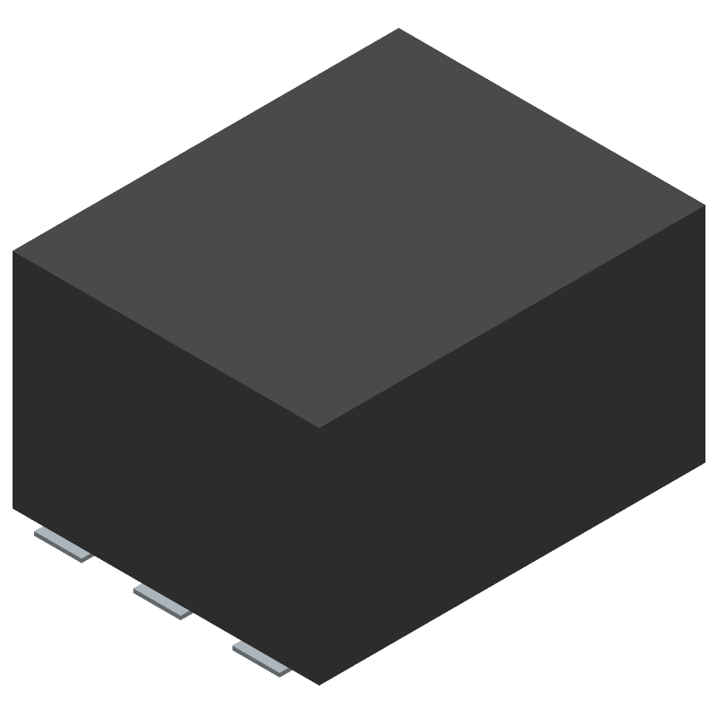
Available Download Formats
By downloading CAD models, you agree to our Terms & Conditions and Privacy Policy
Combiner, 20MHz Min, 2000MHz Max, 1.5dB Insertion Loss-Max, ROHS COMPLIANT, CASE QQQ569, 6 PIN
Tip: Data for a part may vary between manufacturers. You can filter for manufacturers on the top of the page next to the part image and part number.
LRPS-2-11J+ by Mini-Circuits is an RF/Microwave Splitter/Combiner.
RF/Microwave Splitter/Combiners are under the broader part category of RF and Microwave Components.
RF and Microwave Engineering focuses on the design and operation of devices that transmit or receive radio waves. The main distinction between RF and microwave engineering is their wavelength, which influences how energy is transmitted and used in various applications. Read more about RF and Microwave Components on our RF and Microwave part category page.
| Part # | Distributor | Description | Stock | Price | Buy | |
|---|---|---|---|---|---|---|
|
DISTI #
3157-LRPS-2-11J+CT-ND
|
DigiKey | 2 WAYS PWRSPLTR, 20 - 2000 MHZ Min Qty: 1 Lead time: 7 Weeks Container: Cut Tape (CT), Digi-Reel®, Tape & Reel (TR) |
134 In Stock |
|
$27.6602 / $42.0000 | Buy Now |
|
DISTI #
139-LRPS-2-11J+
|
Mouser Electronics | Signal Conditioning 2 Ways Core & Wire Power Splitter, 20 - 2000 MHz, 50? RoHS: Compliant | 319 |
|
$29.2600 / $37.8700 | Buy Now |
|
|
Cytech Systems Limited | 100 |
|
RFQ |
By downloading CAD models, you agree to our Terms & Conditions and Privacy Policy
|
|
LRPS-2-11J+
Mini-Circuits
Buy Now
Datasheet
|
Compare Parts:
LRPS-2-11J+
Mini-Circuits
Combiner, 20MHz Min, 2000MHz Max, 1.5dB Insertion Loss-Max, ROHS COMPLIANT, CASE QQQ569, 6 PIN
|
| Pbfree Code | Yes | |
| Rohs Code | Yes | |
| Part Life Cycle Code | Active | |
| Ihs Manufacturer | MINI-CIRCUITS | |
| Reach Compliance Code | unknown | |
| ECCN Code | EAR99 | |
| Samacsys Manufacturer | Mini-Circuits | |
| Characteristic Impedance | 50 Ω | |
| Construction | COMPONENT | |
| Input Power-Max (CW) | 30 dBm | |
| Insertion Loss-Max | 1.5 dB | |
| Isolation-Min | 15 dB | |
| JESD-609 Code | e3 | |
| Mounting Feature | SURFACE MOUNT | |
| Number of Terminals | 6 | |
| Operating Frequency-Max | 2000 MHz | |
| Operating Frequency-Min | 20 MHz | |
| Operating Temperature-Max | 85 °C | |
| Operating Temperature-Min | -40 °C | |
| Package Equivalence Code | SMDIP6,.4 | |
| RF/Microwave Device Type | SPLITTER AND COMBINER | |
| Surface Mount | YES | |
| Terminal Finish | Tin (Sn) - with Nickel (Ni) barrier | |
| VSWR-Max | 1.58 |
This table gives cross-reference parts and alternative options found for LRPS-2-11J+. The Form Fit Function (FFF) tab will give you the options that are more likely to serve as direct pin-to-pin alternates or drop-in parts. The Functional Equivalents tab will give you options that are likely to match the same function of LRPS-2-11J+, but it may not fit your design. Always verify details of parts you are evaluating, as these parts are offered as suggestions for what you are looking for and are not guaranteed.
| Part Number | Manufacturer | Composite Price | Description | Compare |
|---|---|---|---|---|
| LRPS-2-11J | Mini-Circuits | Check for Price | Combiner, 20MHz Min, 2000MHz Max, 1.5dB Insertion Loss-Max, CASE QQQ569, 6 PIN | LRPS-2-11J+ vs LRPS-2-11J |
Mini-Circuits provides a recommended PCB layout and footprint in their application notes, which can be found on their website. It's essential to follow these guidelines to ensure optimal performance and minimize parasitic effects.
The LRPS-2-11J+ has a 50 ohm input and output impedance. To impedance match, use a pi-network or a T-network topology with resistors and capacitors. You can also use simulation software like ADS or AWR to optimize the matching network.
The maximum power handling of the LRPS-2-11J+ is 1W. Exceeding this power limit can cause damage to the device. Make sure to derate the power handling based on the operating frequency and temperature.
Yes, the LRPS-2-11J+ is designed for high-reliability applications and is suitable for use in space-constrained environments. However, it's essential to follow proper PCB design and assembly practices to ensure reliability and performance.
Common issues with the LRPS-2-11J+ include poor return loss, high insertion loss, or oscillations. To troubleshoot, check the PCB layout, impedance matching, and power handling. Use a vector network analyzer to measure the device's S-parameters and identify the root cause of the issue.