-
Part Symbol
-
Footprint
-
3D Model
Available Download Formats
By downloading CAD models, you agree to our Terms & Conditions and Privacy Policy

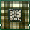
SPECIALTY ANALOG CIRCUIT, PBGA28, 4 X 5 MM, 1 MM HEIGHT, ROHS COMPLIANT, PLASTIC, LGA-28
Tip: Data for a part may vary between manufacturers. You can filter for manufacturers on the top of the page next to the part image and part number.
LPY403AL by STMicroelectronics is an Other Signal Circuit.
Other Signal Circuits are under the broader part category of Signal Circuits.
A signal is an electronic means of transmitting information, either as an analog signal with continuous values or a digital signal with discrete values. Signals are used in various systems and networks. Read more about Signal Circuits on our Signal Circuits part category page.
| Part # | Distributor | Description | Stock | Price | Buy | |
|---|---|---|---|---|---|---|
|
DISTI #
55R4214
|
Newark | Gyroscope, 30Dps, Lga-28, Sensing Axis:Pitch, Yaw, Sensing Range:± 30°/S, Supply Voltage Min:2.7V, Supply Voltage Max:3.6V, Sensor Case/Package:Lga, No. Of Pins:28Pins, Output Interface:-, Operating Temperature Min:-40°C Rohs Compliant: Yes |Stmicroelectronics LPY403AL RoHS: Compliant Min Qty: 2940 Package Multiple: 1 Date Code: 0 Container: Bulk | 0 |
|
Buy Now | |
|
DISTI #
70407371
|
RS | MEMS Motion Sensor PLGA Min Qty: 5 Package Multiple: 1 Container: Bulk | 0 |
|
$5.6400 / $6.3900 | RFQ |
|
|
Vyrian | Other Function Semiconductors | 202 |
|
RFQ |
By downloading CAD models, you agree to our Terms & Conditions and Privacy Policy
|
|
LPY403AL
STMicroelectronics
Buy Now
Datasheet
|
Compare Parts:
LPY403AL
STMicroelectronics
SPECIALTY ANALOG CIRCUIT, PBGA28, 4 X 5 MM, 1 MM HEIGHT, ROHS COMPLIANT, PLASTIC, LGA-28
|
| Pbfree Code | Yes | |
| Rohs Code | Yes | |
| Part Life Cycle Code | Obsolete | |
| Ihs Manufacturer | STMICROELECTRONICS | |
| Part Package Code | LGA | |
| Package Description | 4 X 5 MM, 1 MM HEIGHT, ROHS COMPLIANT, PLASTIC, LGA-28 | |
| Pin Count | 28 | |
| Reach Compliance Code | compliant | |
| HTS Code | 8542.39.00.01 | |
| Samacsys Manufacturer | STMicroelectronics | |
| Analog IC - Other Type | ANALOG CIRCUIT | |
| JESD-30 Code | R-PBGA-B28 | |
| JESD-609 Code | e4 | |
| Length | 5 mm | |
| Moisture Sensitivity Level | 3 | |
| Number of Functions | 1 | |
| Number of Terminals | 28 | |
| Operating Temperature-Max | 85 °C | |
| Operating Temperature-Min | -40 °C | |
| Package Body Material | PLASTIC/EPOXY | |
| Package Code | TFBGA | |
| Package Equivalence Code | LCC28,.16X.2,20 | |
| Package Shape | RECTANGULAR | |
| Package Style | GRID ARRAY | |
| Peak Reflow Temperature (Cel) | 260 | |
| Qualification Status | Not Qualified | |
| Seated Height-Max | 1.1 mm | |
| Supply Voltage-Max (Vsup) | 3.6 V | |
| Supply Voltage-Min (Vsup) | 2.7 V | |
| Supply Voltage-Nom (Vsup) | 3 V | |
| Surface Mount | YES | |
| Technology | CMOS | |
| Temperature Grade | INDUSTRIAL | |
| Terminal Finish | NICKEL GOLD | |
| Terminal Form | BUTT | |
| Terminal Pitch | 0.5 mm | |
| Terminal Position | BOTTOM | |
| Time@Peak Reflow Temperature-Max (s) | 30 | |
| Width | 4 mm |
A symmetrical layout with a central grounding point is recommended. The accelerometer should be placed close to the center of the PCB, and the x, y, and z axes should be aligned with the PCB's axes. A ground plane is also recommended to reduce noise.
Calibration involves applying known accelerations to the device and measuring the output. A calibration matrix can be calculated using the measured data, which can then be used to correct the output of the accelerometer. STMicroelectronics provides a calibration guide in the application note AN2715.
The recommended power-on sequence is to first apply VDD, then VDDIO, and finally enable the device by setting the EN pin high. This ensures that the internal voltage regulators are properly powered up before the device is enabled.
The self-test feature can be enabled by setting the ST pin high. During self-test, the device applies a known acceleration to its internal sensing elements and measures the response. The self-test result can be read from the device's output registers. The self-test feature can be used to verify the device's functionality and detect any faults.
A low-pass filter with a cutoff frequency of around 10-20 Hz is recommended to remove high-frequency noise from the output data. A digital filter, such as a moving average filter or a Gaussian filter, can also be used to further reduce noise and improve the signal-to-noise ratio.