-
Part Symbol
-
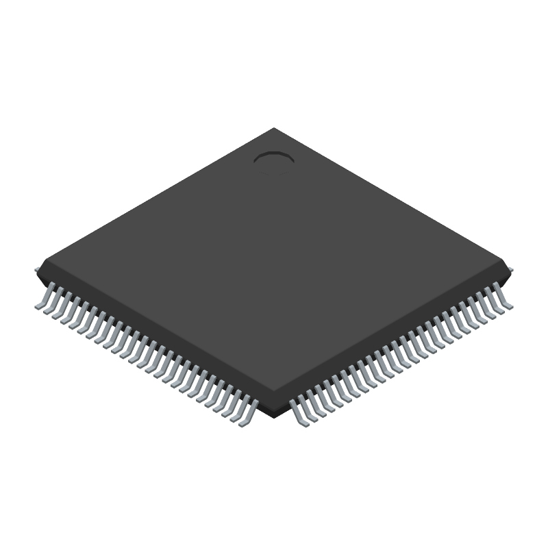
Footprint
-
3D Model
Available Download Formats
By downloading CAD models, you agree to our Terms & Conditions and Privacy Policy

32-BIT, FLASH, 100MHz, RISC MICROCONTROLLER, PQFP100, 14 X 14 MM, 1.40 MM HEIGHT, ROHS COMPLIANT, PLASTIC, SOT-407-1, MS-026, LQFP-100
Tip: Data for a part may vary between manufacturers. You can filter for manufacturers on the top of the page next to the part image and part number.
LPC1767FBD100 by NXP Semiconductors is a Microcontroller.
Microcontrollers are under the broader part category of Microcontrollers and Processors.
Microcontrollers (MCUs) are small, low-power integrated circuits used to control embedded systems. Microcontrollers are primarily used to automate and control devices. Read more about Microcontrollers and Processors on our Microcontrollers and Processors part category page.
| Part # | Distributor | Description | Stock | Price | Buy | |
|---|---|---|---|---|---|---|
|
|
ComSIT USA | 32-BIT ARM CORTEX-M3 MICROCONTROLLER RISC Microcontroller, 32-Bit, FLASH, 100MHz, CMOS, PQFP100 ECCN: EAR99 RoHS: Compliant |
|
|
RFQ | |
|
|
Flip Electronics | Stock, ship today | 8460 |
|
RFQ |
By downloading CAD models, you agree to our Terms & Conditions and Privacy Policy
|
|
LPC1767FBD100
NXP Semiconductors
Buy Now
Datasheet
|
Compare Parts:
LPC1767FBD100
NXP Semiconductors
32-BIT, FLASH, 100MHz, RISC MICROCONTROLLER, PQFP100, 14 X 14 MM, 1.40 MM HEIGHT, ROHS COMPLIANT, PLASTIC, SOT-407-1, MS-026, LQFP-100
|
| Rohs Code | Yes | |
| Part Life Cycle Code | Active | |
| Ihs Manufacturer | NXP SEMICONDUCTORS | |
| Part Package Code | QFP | |
| Package Description | LQFP-100 | |
| Pin Count | 100 | |
| Reach Compliance Code | compliant | |
| ECCN Code | 3A991.A.2 | |
| HTS Code | 8542.31.00.01 | |
| Factory Lead Time | 2 Days | |
| Samacsys Manufacturer | NXP | |
| Has ADC | YES | |
| Address Bus Width | ||
| Bit Size | 32 | |
| Clock Frequency-Max | 25 MHz | |
| DAC Channels | YES | |
| DMA Channels | YES | |
| External Data Bus Width | ||
| JESD-30 Code | S-PQFP-G100 | |
| Length | 14 mm | |
| Moisture Sensitivity Level | 3 | |
| Number of I/O Lines | 70 | |
| Number of Terminals | 100 | |
| Operating Temperature-Max | 85 °C | |
| Operating Temperature-Min | -40 °C | |
| PWM Channels | YES | |
| Package Body Material | PLASTIC/EPOXY | |
| Package Code | LFQFP | |
| Package Shape | SQUARE | |
| Package Style | FLATPACK, LOW PROFILE, FINE PITCH | |
| Peak Reflow Temperature (Cel) | NOT SPECIFIED | |
| Qualification Status | Not Qualified | |
| ROM Programmability | FLASH | |
| Seated Height-Max | 1.6 mm | |
| Speed | 100 MHz | |
| Supply Voltage-Max | 3.6 V | |
| Supply Voltage-Min | 2.4 V | |
| Supply Voltage-Nom | 3.3 V | |
| Surface Mount | YES | |
| Technology | CMOS | |
| Temperature Grade | INDUSTRIAL | |
| Terminal Finish | Pure Tin (Sn) | |
| Terminal Form | GULL WING | |
| Terminal Pitch | 0.5 mm | |
| Terminal Position | QUAD | |
| Time@Peak Reflow Temperature-Max (s) | NOT SPECIFIED | |
| Width | 14 mm | |
| uPs/uCs/Peripheral ICs Type | MICROCONTROLLER, RISC |
The maximum clock frequency that can be achieved with the internal oscillator is 25 MHz. However, it's recommended to use an external crystal oscillator for frequencies above 12 MHz for better accuracy and stability.
To configure the USB interface to work in device mode, you need to set the USB_MODE pin high, enable the USB clock, and configure the USB registers accordingly. You can refer to the USB chapter in the user manual for more details.
The maximum amount of current that can be sourced or sunk by the GPIO pins is 4 mA. However, it's recommended to limit the current to 2 mA or less to ensure reliable operation and prevent overheating.
To use the ADC in differential mode, you need to configure the ADC registers to select the differential input channels, and set the ADC mode to differential. You also need to ensure that the input signals are within the specified common-mode voltage range.
The minimum voltage range for the ADC inputs is 0 V, and the maximum voltage range is VCC (typically 3.3 V or 5 V). However, the recommended input voltage range is 0 V to VCC - 1.5 V to ensure accurate conversions.