-
Part Symbol
-
Footprint
-
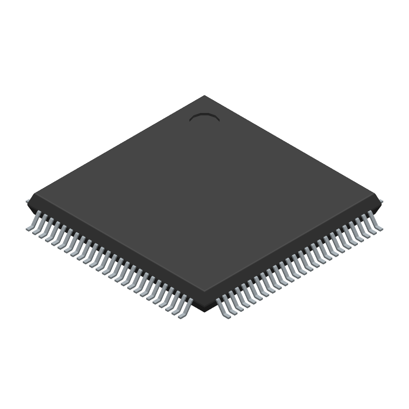
3D Model
Available Download Formats
By downloading CAD models, you agree to our Terms & Conditions and Privacy Policy

IC RISC MICROCONTROLLER, Microcontroller
Tip: Data for a part may vary between manufacturers. You can filter for manufacturers on the top of the page next to the part image and part number.
LPC11U68JBD100 by NXP Semiconductors is a Microcontroller.
Microcontrollers are under the broader part category of Microcontrollers and Processors.
Microcontrollers (MCUs) are small, low-power integrated circuits used to control embedded systems. Microcontrollers are primarily used to automate and control devices. Read more about Microcontrollers and Processors on our Microcontrollers and Processors part category page.
| Part # | Distributor | Description | Stock | Price | Buy | |
|---|---|---|---|---|---|---|
|
|
Vyrian | Peripheral ICs | 616 |
|
RFQ |
By downloading CAD models, you agree to our Terms & Conditions and Privacy Policy
|
|
LPC11U68JBD100
NXP Semiconductors
Buy Now
Datasheet
|
Compare Parts:
LPC11U68JBD100
NXP Semiconductors
IC RISC MICROCONTROLLER, Microcontroller
|
| Rohs Code | Yes | |
| Part Life Cycle Code | Active | |
| Ihs Manufacturer | NXP SEMICONDUCTORS | |
| Package Description | LQFP100 | |
| Reach Compliance Code | compliant | |
| ECCN Code | 3A991.A.2 | |
| HTS Code | 8542.31.00.01 | |
| Samacsys Manufacturer | NXP | |
| Has ADC | YES | |
| Address Bus Width | ||
| Bit Size | 32 | |
| Boundary Scan | YES | |
| CPU Family | CORTEX-M0 | |
| Clock Frequency-Max | 25 MHz | |
| DAC Channels | NO | |
| DMA Channels | YES | |
| External Data Bus Width | ||
| Format | FIXED POINT | |
| Integrated Cache | YES | |
| JESD-30 Code | S-PQFP-G100 | |
| JESD-609 Code | e3 | |
| Length | 14 mm | |
| Low Power Mode | YES | |
| Moisture Sensitivity Level | 3 | |
| Number of DMA Channels | 16 | |
| Number of External Interrupts | 8 | |
| Number of I/O Lines | 80 | |
| Number of Serial I/Os | 5 | |
| Number of Terminals | 100 | |
| Number of Timers | 7 | |
| On Chip Data RAM Width | 8 | |
| On Chip Program ROM Width | 8 | |
| Operating Temperature-Max | 105 °C | |
| Operating Temperature-Min | -40 °C | |
| PWM Channels | YES | |
| Package Body Material | PLASTIC/EPOXY | |
| Package Code | LFQFP | |
| Package Equivalence Code | QFP100,.63SQ,20 | |
| Package Shape | SQUARE | |
| Package Style | FLATPACK, LOW PROFILE, FINE PITCH | |
| Peak Reflow Temperature (Cel) | 260 | |
| RAM (bytes) | 36864 | |
| ROM (words) | 262144 | |
| ROM Programmability | FLASH | |
| Seated Height-Max | 1.6 mm | |
| Speed | 50 MHz | |
| Supply Current-Max | 100 mA | |
| Supply Voltage-Max | 3.6 V | |
| Supply Voltage-Min | 2.4 V | |
| Supply Voltage-Nom | 3.3 V | |
| Surface Mount | YES | |
| Technology | CMOS | |
| Temperature Grade | INDUSTRIAL | |
| Terminal Finish | TIN | |
| Terminal Form | GULL WING | |
| Terminal Pitch | 0.5 mm | |
| Terminal Position | QUAD | |
| Time@Peak Reflow Temperature-Max (s) | 30 | |
| Width | 14 mm | |
| uPs/uCs/Peripheral ICs Type | MICROCONTROLLER, RISC |
The internal oscillator can be configured to run up to 12 MHz, but the maximum clock frequency that can be achieved depends on the specific configuration and the quality of the external crystal used. Typically, it can reach up to 10 MHz.
To configure the USB interface to work in device mode, you need to set the USB_MODE pin high, enable the USB clock, and configure the USB registers to enable device mode. You can refer to the USB chapter in the user manual for more details.
The maximum amount of current that can be sourced or sunk by the GPIO pins is 4 mA per pin, with a total current limit of 100 mA for all GPIO pins combined.
To use the ADC, you need to configure the ADC clock, select the ADC channel, set the ADC resolution, and start the ADC conversion. You can then read the converted digital value from the ADC result register. Refer to the ADC chapter in the user manual for more details.
The BOOT pin is used to select the boot mode of the microcontroller. When the BOOT pin is pulled low, the microcontroller boots from the internal flash memory. When it is pulled high, the microcontroller boots from the external memory or serial interface. You can use the BOOT pin to select the boot mode depending on your application requirements.