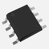
Part Details for LNK624DG by Power Integrations
Results Overview of LNK624DG by Power Integrations
- Distributor Offerings: (3 listings)
- Number of FFF Equivalents: (0 replacements)
- CAD Models: (Request Part)
- Number of Functional Equivalents: (6 options)
- Part Data Attributes: (Available)
- Reference Designs: (Not Available)
Tip: Data for a part may vary between manufacturers. You can filter for manufacturers on the top of the page next to the part image and part number.
LNK624DG Information
LNK624DG by Power Integrations is an Other Signal Circuit.
Other Signal Circuits are under the broader part category of Signal Circuits.
A signal is an electronic means of transmitting information, either as an analog signal with continuous values or a digital signal with discrete values. Signals are used in various systems and networks. Read more about Signal Circuits on our Signal Circuits part category page.
Price & Stock for LNK624DG
| Part # | Distributor | Description | Stock | Price | Buy | |
|---|---|---|---|---|---|---|
|
DISTI #
596-1251-5-ND
|
DigiKey | IC OFFLINE SWITCH FLYBACK 8SO Lead time: 4 Weeks Container: Tube | Limited Supply - Call |
|
Buy Now | |
|
|
Bristol Electronics | 30 |
|
RFQ | ||
|
DISTI #
LNK624DG
|
EBV Elektronik | Off Line Switcher 7Pin SOICC (Alt: LNK624DG) RoHS: Compliant Min Qty: 100 Package Multiple: 100 | EBV - 0 |
|
Buy Now |
Part Details for LNK624DG
LNK624DG CAD Models
LNK624DG Part Data Attributes
|
|
LNK624DG
Power Integrations
Buy Now
Datasheet
|
Compare Parts:
LNK624DG
Power Integrations
Analog Circuit, 1 Func, PDSO7, SOP-8/7
|
| Pbfree Code | Yes | |
| Rohs Code | Yes | |
| Part Life Cycle Code | Active | |
| Ihs Manufacturer | POWER INTEGRATIONS INC | |
| Part Package Code | SOIC | |
| Pin Count | 8/7 | |
| Reach Compliance Code | compliant | |
| ECCN Code | EAR99 | |
| HTS Code | 8542.39.00.01 | |
| Samacsys Manufacturer | Power Integrations | |
| Analog IC - Other Type | POWER SUPPLY SUPPORT CIRCUIT | |
| JESD-609 Code | e3 | |
| Moisture Sensitivity Level | 1 | |
| Peak Reflow Temperature (Cel) | 260 | |
| Terminal Finish | MATTE TIN | |
| Time@Peak Reflow Temperature-Max (s) | 40 |
Alternate Parts for LNK624DG
This table gives cross-reference parts and alternative options found for LNK624DG. The Form Fit Function (FFF) tab will give you the options that are more likely to serve as direct pin-to-pin alternates or drop-in parts. The Functional Equivalents tab will give you options that are likely to match the same function of LNK624DG, but it may not fit your design. Always verify details of parts you are evaluating, as these parts are offered as suggestions for what you are looking for and are not guaranteed.
| Part Number | Manufacturer | Composite Price | Description | Compare |
|---|---|---|---|---|
| LNK623DG-TL | Power Integrations | $0.7797 | Analog Circuit, 1 Func, PDSO7, SOP-8/7 | LNK624DG vs LNK623DG-TL |
| LNK625DG-TL | Power Integrations | $0.8701 | Analog Circuit, 1 Func, PDSO7, SOP-8/7 | LNK624DG vs LNK625DG-TL |
| LNK625PG | Power Integrations | $0.9189 | Analog Circuit, 1 Func, PDIP7, DIP-8/7 | LNK624DG vs LNK625PG |
| LNK623PG | Power Integrations | $1.0269 | Analog Circuit, 1 Func, PDIP7, DIP-8/7 | LNK624DG vs LNK623PG |
| LNK626PG | Power Integrations | $1.3018 | Analog Circuit, 1 Func, PDIP7, DIP-8/7 | LNK624DG vs LNK626PG |
| LNK626DG | Power Integrations | Check for Price | Analog Circuit, 1 Func, PDSO7, SOP-8/7 | LNK624DG vs LNK626DG |
LNK624DG Frequently Asked Questions (FAQ)
-
The maximum output power of LNK624DG depends on the input voltage, output voltage, and other design parameters. However, Power Integrations recommends a maximum output power of 65W for this device.
-
To ensure reliable start-up, make sure the input voltage is within the recommended range, the input capacitor is properly sized, and the output voltage is properly regulated. Also, ensure that the device is properly cooled and the thermal design is adequate.
-
Power Integrations recommends a 2-layer or 4-layer PCB with a solid ground plane and a separate layer for the high-voltage traces. Keep the high-voltage traces short and away from sensitive analog circuits. Follow the recommended layout guidelines in the datasheet and application notes.
-
To optimize the design for EMI and EMC compliance, use a shielded transformer, keep the layout compact, and use a common-mode choke. Also, ensure that the device is properly grounded and the PCB is designed to minimize radiation. Follow the recommended EMI and EMC guidelines in the datasheet and application notes.
-
The recommended input capacitor value is 10uF to 22uF, and the type should be a low-ESR ceramic or film capacitor. The capacitor should be rated for the maximum input voltage and should be placed close to the device.
