-
Part Symbol
-
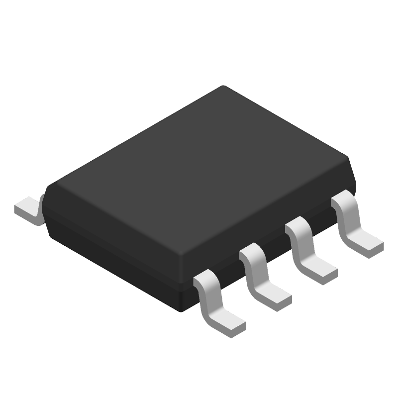
Footprint
-
3D Model
Available Download Formats
By downloading CAD models, you agree to our Terms & Conditions and Privacy Policy

SIMPLE SWITCHER® Automotive 40-V, 2-A, 2.2-MHz step-down converter with 40-uA IQ 8-SO PowerPAD -40 to 125
Tip: Data for a part may vary between manufacturers. You can filter for manufacturers on the top of the page next to the part image and part number.
LMR14020SSQDDARQ1 by Texas Instruments is a Switching Regulator or Controller.
Switching Regulator or Controllers are under the broader part category of Power Circuits.
A power circuit delivers electricity in order to operate a load for an electronic device. Power circuits include transformers, generators and switches. Read more about Power Circuits on our Power Circuits part category page.
| Part # | Distributor | Description | Stock | Price | Buy | |
|---|---|---|---|---|---|---|
|
DISTI #
296-43399-1-ND
|
DigiKey | IC REG BUCK ADJ 2A 8SOPWR Min Qty: 1 Lead time: 12 Weeks Container: Digi-Reel®, Cut Tape (CT), Tape & Reel (TR) |
2849 In Stock |
|
$1.3575 / $2.8300 | Buy Now |
|
DISTI #
595-LMR14020SSDDARQ1
|
Mouser Electronics | Switching Voltage Regulators SIMPLE SWITCHER Aut omotive 40-V 2-A 2 A 595-LMR14020SSQDDAQ1 RoHS: Compliant | 845 |
|
$1.3300 / $3.9600 | Buy Now |
|
DISTI #
LMR14020SSQDDARQ1
|
TME | PMIC, DC/DC converter, Uin: 4÷40VDC, Uout: 0.8÷28VDC, 2A, HSOIC8-EP Min Qty: 2500 | 0 |
|
$1.8200 | RFQ |
|
|
ComSIT USA | SIMPLE SWITCHER 40 V, 2 A STEP-DOWN CONVERTER WITH 40 UA IQ Switching Regulator, Current-mode, 2A, 2500kHz Switching Freq-Max, PDSO8 ECCN: EAR99 RoHS: Compliant |
|
|
RFQ | |
|
|
Vyrian | Other Function Semiconductors | 3338 |
|
RFQ | |
|
|
Win Source Electronics | IC REG BUCK ADJUSTABLE 2A 8SOPWR / SIMPLE SWITCHER® 40 V, 2 A Step-Down Converter | 1700 |
|
$3.5952 / $5.3928 | Buy Now |
By downloading CAD models, you agree to our Terms & Conditions and Privacy Policy
|
|
LMR14020SSQDDARQ1
Texas Instruments
Buy Now
Datasheet
|
Compare Parts:
LMR14020SSQDDARQ1
Texas Instruments
SIMPLE SWITCHER® Automotive 40-V, 2-A, 2.2-MHz step-down converter with 40-uA IQ 8-SO PowerPAD -40 to 125
|
| Pbfree Code | Yes | |
| Rohs Code | Yes | |
| Part Life Cycle Code | Active | |
| Ihs Manufacturer | TEXAS INSTRUMENTS INC | |
| Reach Compliance Code | compliant | |
| ECCN Code | EAR99 | |
| HTS Code | 8542.39.00.01 | |
| Samacsys Manufacturer | Texas Instruments | |
| Additional Feature | ALSO OPERATES IN ADJUSTABLE MODE FROM 0.8 TO 28V | |
| Analog IC - Other Type | SWITCHING REGULATOR | |
| Control Mode | CURRENT-MODE | |
| Control Technique | PULSE WIDTH MODULATION | |
| Input Voltage-Max | 40 V | |
| Input Voltage-Min | 4 V | |
| Input Voltage-Nom | 12 V | |
| JESD-30 Code | R-PDSO-G8 | |
| JESD-609 Code | e4 | |
| Moisture Sensitivity Level | 2 | |
| Number of Functions | 1 | |
| Number of Outputs | 1 | |
| Number of Terminals | 8 | |
| Operating Temperature-Max | 125 °C | |
| Operating Temperature-Min | -40 °C | |
| Output Current-Max | 2 A | |
| Output Voltage-Max | 28 V | |
| Output Voltage-Min | 0.8 V | |
| Package Body Material | PLASTIC/EPOXY | |
| Package Code | HSOP | |
| Package Shape | RECTANGULAR | |
| Package Style | SMALL OUTLINE, HEAT SINK/SLUG | |
| Peak Reflow Temperature (Cel) | 260 | |
| Screening Level | AEC-Q100 | |
| Surface Mount | YES | |
| Switcher Configuration | BUCK | |
| Switching Frequency-Max | 2500 kHz | |
| Temperature Grade | AUTOMOTIVE | |
| Terminal Finish | Nickel/Palladium/Gold/Silver (Ni/Pd/Au/Ag) | |
| Terminal Form | GULL WING | |
| Terminal Pitch | 1.27 mm | |
| Terminal Position | DUAL | |
| Time@Peak Reflow Temperature-Max (s) | 30 |
A good PCB layout for optimal thermal performance involves placing the device near a thermal pad or a heat sink, and ensuring good thermal conductivity between the device and the PCB. A 2-layer or 4-layer PCB with a solid ground plane is recommended. Additionally, placing vias under the device can help to dissipate heat more efficiently.
To ensure the device operates within the recommended operating conditions, it's essential to monitor the input voltage, output voltage, and output current. The input voltage should be within the recommended range of 4.5V to 42V, and the output voltage should be within the recommended range of 0.8V to 40V. The output current should not exceed the recommended maximum current rating of 2A.
When handling the device, it's essential to take precautions to prevent damage from electrostatic discharge (ESD). Use an ESD wrist strap or mat, and handle the device by the body or pins, rather than the leads. Avoid touching the device's pins or leads, and store the device in an anti-static bag or container when not in use.
To troubleshoot issues with the device, start by checking the input voltage, output voltage, and output current. Verify that the input voltage is within the recommended range, and that the output voltage and current are within the expected ranges. Check for any signs of overheating, and ensure that the device is properly soldered to the PCB. If the issue persists, consult the datasheet and application notes for further guidance.
The device has a maximum junction temperature rating of 150°C. To ensure reliable operation, it's essential to keep the junction temperature below this rating. Use a heat sink or thermal pad to dissipate heat, and ensure good airflow around the device. Avoid operating the device in high-temperature environments, and monitor the device's temperature using a thermocouple or thermal sensor.