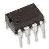
Part Details for LM2574HVN-12 by Texas Instruments
Results Overview of LM2574HVN-12 by Texas Instruments
- Distributor Offerings: (1 listing)
- Number of FFF Equivalents: (0 replacements)
- CAD Models: (Request Part)
- Number of Functional Equivalents: (0 options)
- Part Data Attributes: (Available)
- Reference Designs: (Not Available)
Tip: Data for a part may vary between manufacturers. You can filter for manufacturers on the top of the page next to the part image and part number.
LM2574HVN-12 Information
LM2574HVN-12 by Texas Instruments is a Switching Regulator or Controller.
Switching Regulator or Controllers are under the broader part category of Power Circuits.
A power circuit delivers electricity in order to operate a load for an electronic device. Power circuits include transformers, generators and switches. Read more about Power Circuits on our Power Circuits part category page.
Available Datasheets
| Part # | Manufacturer | Description | Datasheet |
|---|---|---|---|
| LM2574HVN-15/NOPB | Texas Instruments | SIMPLE SWITCHER 0.5A Step-Down Voltage Regulator 8-PDIP -40 to 125 | |
| LM2574HVN-12/NOPB | Texas Instruments | SIMPLE SWITCHER 0.5A Step-Down Voltage Regulator 8-PDIP -40 to 125 | |
| LM2574HVN-5.0/NOPB | Texas Instruments | SIMPLE SWITCHER 0.5A Step-Down Voltage Regulator 8-PDIP -40 to 125 |
Price & Stock for LM2574HVN-12
| Part # | Distributor | Description | Stock | Price | Buy | |
|---|---|---|---|---|---|---|
|
|
Rochester Electronics | LM2574HV SIMPLE SWITCHER 0.5A Step-Down Voltage Regulator RoHS: Not Compliant Status: Obsolete Min Qty: 1 | 55 |
|
$2.0900 / $2.6100 | Buy Now |
Part Details for LM2574HVN-12
LM2574HVN-12 CAD Models
LM2574HVN-12 Part Data Attributes
|
|
LM2574HVN-12
Texas Instruments
Buy Now
Datasheet
|
Compare Parts:
LM2574HVN-12
Texas Instruments
1.8A SWITCHING REGULATOR, 63kHz SWITCHING FREQ-MAX, PDIP8, DIP-8
|
| Pbfree Code | No | |
| Rohs Code | No | |
| Part Life Cycle Code | Obsolete | |
| Ihs Manufacturer | TEXAS INSTRUMENTS INC | |
| Part Package Code | DIP | |
| Package Description | DIP-8 | |
| Pin Count | 8 | |
| Reach Compliance Code | not_compliant | |
| ECCN Code | EAR99 | |
| HTS Code | 8542.39.00.01 | |
| Analog IC - Other Type | SWITCHING REGULATOR | |
| Control Mode | VOLTAGE-MODE | |
| Control Technique | PULSE WIDTH MODULATION | |
| Input Voltage-Max | 60 V | |
| Input Voltage-Min | 15 V | |
| Input Voltage-Nom | 25 V | |
| JESD-30 Code | R-PDIP-T8 | |
| JESD-609 Code | e0 | |
| Length | 9.817 mm | |
| Moisture Sensitivity Level | 1 | |
| Number of Functions | 1 | |
| Number of Terminals | 8 | |
| Operating Temperature-Max | 125 °C | |
| Operating Temperature-Min | -40 °C | |
| Output Current-Max | 1.8 A | |
| Output Voltage-Max | 12.66 V | |
| Output Voltage-Min | 11.4 V | |
| Output Voltage-Nom | 12 V | |
| Package Body Material | PLASTIC/EPOXY | |
| Package Code | DIP | |
| Package Equivalence Code | DIP8,.3 | |
| Package Shape | RECTANGULAR | |
| Package Style | IN-LINE | |
| Qualification Status | Not Qualified | |
| Seated Height-Max | 5.08 mm | |
| Surface Mount | NO | |
| Switcher Configuration | BUCK | |
| Switching Frequency-Max | 63 kHz | |
| Technology | BIPOLAR | |
| Temperature Grade | AUTOMOTIVE | |
| Terminal Finish | TIN LEAD | |
| Terminal Form | THROUGH-HOLE | |
| Terminal Pitch | 2.54 mm | |
| Terminal Position | DUAL | |
| Width | 7.62 mm |
LM2574HVN-12 Frequently Asked Questions (FAQ)
-
The maximum input voltage that can be applied to the LM2574HVN-12 is 40V, but it's recommended to keep it below 37V to ensure reliable operation.
-
To ensure the output voltage is stable and accurate, make sure to use a stable input voltage, choose the correct output capacitor value, and keep the feedback resistors within the recommended range.
-
The minimum input voltage required for the LM2574HVN-12 to operate is around 7V, but it's recommended to keep it above 8V for reliable startup and operation.
-
The LM2574HVN-12 is rated for operation up to 125°C, but it's recommended to derate the output current and input voltage as the temperature increases to ensure reliable operation.
-
The output voltage ripple of the LM2574HVN-12 can be calculated using the formula: ΔVout = (Iout * Rcoil) / (2 * fsw * Cout), where Iout is the output current, Rcoil is the inductor resistance, fsw is the switching frequency, and Cout is the output capacitor value.
