-
Part Symbol
-
Footprint
-
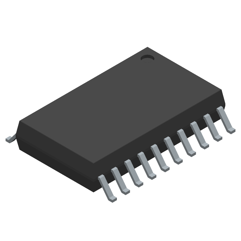
3D Model
Available Download Formats
By downloading CAD models, you agree to our Terms & Conditions and Privacy Policy

Buffer/Inverter Based Peripheral Driver, 8.5A, PDSO20, GREEN, PLASTIC, SOP-20
Tip: Data for a part may vary between manufacturers. You can filter for manufacturers on the top of the page next to the part image and part number.
ITS724GFUMA1 by Infineon Technologies AG is a Peripheral Driver.
Peripheral Drivers are under the broader part category of Drivers And Interfaces.
A driver controls the current or voltage delivered to components like LCDs or motors, while an interface component connects systems for data transfer and control. Read more about Drivers And Interfaces on our Drivers And Interfaces part category page.
| Part # | Distributor | Description | Stock | Price | Buy | |
|---|---|---|---|---|---|---|
|
DISTI #
47W3492
|
Newark | Power Load Sw, High Side, 16V, Soic-20, Power Load Switch Type:High Side, No. Of Channels:4Channels, Input Voltage:16V, Current Limit:15A, On State Resistance:0.09Ohm, Ic Case/Package:Soic, No. Of Pins:20Pins, Product Range:- Rohs Compliant: Yes |Infineon ITS724GFUMA1 RoHS: Compliant Min Qty: 1 Package Multiple: 1 Date Code: 0 Container: Bulk | 8881 |
|
$1.9300 / $3.3400 | Buy Now |
|
DISTI #
ITS724GFUMA1CT-ND
|
DigiKey | IC PWR SWITCH N-CHAN 1:1 DSO-20 Min Qty: 1 Lead time: 26 Weeks Container: Cut Tape (CT), Digi-Reel®, Tape & Reel (TR) |
8419 In Stock |
|
$2.1852 / $4.0300 | Buy Now |
|
DISTI #
ITS724GFUMA1
|
Avnet Americas | - Tape and Reel (Alt: ITS724GFUMA1) RoHS: Compliant Min Qty: 1000 Package Multiple: 1000 Lead time: 26 Weeks, 0 Days Container: Reel | 0 |
|
$1.8528 / $1.9749 | Buy Now |
|
DISTI #
726-ITS724GFUMA1
|
Mouser Electronics | Power Switch ICs - Power Distribution SMART HI SIDE PWR SWITCH INDUSTRY APP RoHS: Compliant | 7527 |
|
$2.1800 / $3.8300 | Buy Now |
|
DISTI #
E02:0323_00172153
|
Arrow Electronics | Current Limit SW 4-IN 4-OUT -10V to 16V 3.3A 20-Pin DSO T/R RoHS: Compliant Min Qty: 1000 Package Multiple: 1000 Lead time: 26 Weeks Date Code: 2513 | Europe - 2000 |
|
$2.1198 / $2.2704 | Buy Now |
|
DISTI #
V72:2272_06378185
|
Arrow Electronics | Current Limit SW 4-IN 4-OUT -10V to 16V 3.3A 20-Pin DSO T/R RoHS: Compliant Min Qty: 1 Package Multiple: 1 Lead time: 26 Weeks Date Code: 2342 Container: Cut Strips | Americas - 698 |
|
$2.0680 / $2.7600 | Buy Now |
|
DISTI #
E32:1076_00172153
|
Arrow Electronics | Current Limit SW 4-IN 4-OUT -10V to 16V 3.3A 20-Pin DSO T/R RoHS: Compliant Min Qty: 1 Package Multiple: 1 Lead time: 26 Weeks Date Code: 2451 | Europe - 44 |
|
$2.0516 / $3.7641 | Buy Now |
|
DISTI #
87630538
|
Verical | Current Limit SW 4-IN 4-OUT -10V to 16V 3.3A 20-Pin DSO T/R RoHS: Compliant Min Qty: 1000 Package Multiple: 1000 Date Code: 2401 | Americas - 6000 |
|
$2.5957 | Buy Now |
|
DISTI #
88152782
|
Verical | Current Limit SW 4-IN 4-OUT -10V to 16V 3.3A 20-Pin DSO T/R RoHS: Compliant Min Qty: 1000 Package Multiple: 1000 Date Code: 2513 | Americas - 2000 |
|
$2.1126 / $2.2627 | Buy Now |
|
DISTI #
76893231
|
Verical | Current Limit SW 4-IN 4-OUT -10V to 16V 3.3A 20-Pin DSO T/R RoHS: Compliant Min Qty: 3 Package Multiple: 1 Date Code: 2342 | Americas - 698 |
|
$2.0680 / $2.7600 | Buy Now |
By downloading CAD models, you agree to our Terms & Conditions and Privacy Policy
|
|
ITS724GFUMA1
Infineon Technologies AG
Buy Now
Datasheet
|
Compare Parts:
ITS724GFUMA1
Infineon Technologies AG
Buffer/Inverter Based Peripheral Driver, 8.5A, PDSO20, GREEN, PLASTIC, SOP-20
|
| Pbfree Code | Yes | |
| Rohs Code | Yes | |
| Part Life Cycle Code | Active | |
| Ihs Manufacturer | INFINEON TECHNOLOGIES AG | |
| Part Package Code | SOIC | |
| Package Description | GREEN, PLASTIC, SOP-20 | |
| Pin Count | 20 | |
| Reach Compliance Code | compliant | |
| ECCN Code | EAR99 | |
| HTS Code | 8542.39.00.01 | |
| Factory Lead Time | 26 Weeks | |
| Samacsys Manufacturer | Infineon | |
| Built-in Protections | TRANSIENT; OVER CURRENT; OVER VOLTAGE; THERMAL; UNDER VOLTAGE | |
| Interface IC Type | BUFFER OR INVERTER BASED PERIPHERAL DRIVER | |
| JESD-30 Code | R-PDSO-G20 | |
| JESD-609 Code | e3 | |
| Length | 12.8 mm | |
| Moisture Sensitivity Level | 3 | |
| Number of Functions | 4 | |
| Number of Terminals | 20 | |
| Operating Temperature-Max | 85 °C | |
| Operating Temperature-Min | -30 °C | |
| Output Current Flow Direction | SINK | |
| Output Peak Current Limit-Nom | 8.5 A | |
| Package Body Material | PLASTIC/EPOXY | |
| Package Code | SOP | |
| Package Equivalence Code | SOP20,.4 | |
| Package Shape | RECTANGULAR | |
| Package Style | SMALL OUTLINE | |
| Qualification Status | Not Qualified | |
| Seated Height-Max | 2.65 mm | |
| Supply Voltage-Max | 40 V | |
| Supply Voltage-Min | 5.5 V | |
| Supply Voltage-Nom | 12 V | |
| Surface Mount | YES | |
| Temperature Grade | COMMERCIAL EXTENDED | |
| Terminal Finish | Tin (Sn) | |
| Terminal Form | GULL WING | |
| Terminal Pitch | 1.27 mm | |
| Terminal Position | DUAL | |
| Turn-off Time | 270 µs | |
| Turn-on Time | 250 µs | |
| Width | 7.6 mm |
A 4-layer PCB with a solid ground plane and thermal vias is recommended for optimal thermal performance. The device should be placed near a thermal pad or a heat sink to dissipate heat efficiently.
To ensure reliable operation in high-temperature environments, it is essential to follow the recommended thermal design guidelines, use a heat sink if necessary, and ensure good airflow around the device. Additionally, consider using a thermal interface material to improve heat transfer between the device and the heat sink.
To prevent ESD damage, handle the device in an ESD-protected environment, wear an ESD strap or wrist strap, and use ESD-safe packaging materials. Avoid touching the device's pins or leads, and use an ESD-safe workstation or mat.
To troubleshoot issues with the device's output voltage regulation, check the input voltage, output voltage, and output current. Verify that the device is properly configured and that the output capacitors are of sufficient value and type. Also, check for any signs of overheating or thermal shutdown.
When using the device in a high-reliability or safety-critical application, consider implementing redundant systems, using error detection and correction mechanisms, and following relevant industry standards and guidelines. Additionally, ensure that the device is properly derated and that the system is designed to tolerate single-point failures.