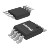
Part Details for ISL267817IUZ-T by Intersil Corporation
Results Overview of ISL267817IUZ-T by Intersil Corporation
- Distributor Offerings: (0 listings)
- Number of FFF Equivalents: (0 replacements)
- CAD Models: (Request Part)
- Number of Functional Equivalents: (0 options)
- Part Data Attributes: (Available)
- Reference Designs: (Not Available)
Tip: Data for a part may vary between manufacturers. You can filter for manufacturers on the top of the page next to the part image and part number.
ISL267817IUZ-T Information
ISL267817IUZ-T by Intersil Corporation is an Analog to Digital Converter.
Analog to Digital Converters are under the broader part category of Converters.
A converter is an electrical circuit that transforms electric energy into a different form that will support a elecrical load needed by a device. Read more about Converters on our Converters part category page.
Part Details for ISL267817IUZ-T
ISL267817IUZ-T CAD Models
ISL267817IUZ-T Part Data Attributes
|
|
ISL267817IUZ-T
Intersil Corporation
Buy Now
Datasheet
|
Compare Parts:
ISL267817IUZ-T
Intersil Corporation
12-Bit Differential Input 200kSPS SAR ADC; MSOP8, SOIC8; Temp Range: -40° to 85°C
|
| Rohs Code | Yes | |
| Part Life Cycle Code | Transferred | |
| Ihs Manufacturer | INTERSIL CORP | |
| Part Package Code | MSOP, SOIC | |
| Package Description | ROHS COMPLIANT, PLASTIC, MO-187AA, MSOP-8 | |
| Pin Count | 8, 8 | |
| Reach Compliance Code | compliant | |
| HTS Code | 8542.39.00.01 | |
| Analog Input Voltage-Max | 2.5 V | |
| Analog Input Voltage-Min | -0.1 V | |
| Conversion Time-Max | 3.75 µs | |
| Converter Type | ADC, SUCCESSIVE APPROXIMATION | |
| JESD-30 Code | S-PDSO-G8 | |
| JESD-609 Code | e3 | |
| Length | 3 mm | |
| Linearity Error-Max (EL) | 0.0244% | |
| Moisture Sensitivity Level | 1 | |
| Number of Analog In Channels | 1 | |
| Number of Bits | 12 | |
| Number of Functions | 1 | |
| Number of Terminals | 8 | |
| Operating Temperature-Max | 85 °C | |
| Operating Temperature-Min | -40 °C | |
| Output Bit Code | 2'S COMPLEMENT BINARY | |
| Output Format | SERIAL | |
| Package Body Material | PLASTIC/EPOXY | |
| Package Code | TSSOP | |
| Package Shape | SQUARE | |
| Package Style | SMALL OUTLINE, THIN PROFILE, SHRINK PITCH | |
| Peak Reflow Temperature (Cel) | 260 | |
| Sample Rate | 0.2 MHz | |
| Sample and Hold / Track and Hold | TRACK | |
| Seated Height-Max | 1.1 mm | |
| Supply Voltage-Nom | 5 V | |
| Surface Mount | YES | |
| Temperature Grade | INDUSTRIAL | |
| Terminal Finish | Matte Tin (Sn) - annealed | |
| Terminal Form | GULL WING | |
| Terminal Pitch | 0.65 mm | |
| Terminal Position | DUAL | |
| Time@Peak Reflow Temperature-Max (s) | 30 | |
| Width | 3 mm |
ISL267817IUZ-T Frequently Asked Questions (FAQ)
-
The recommended PCB layout for optimal performance can be found in the application note AN1325 from Intersil Corporation, which provides guidelines for layout, component placement, and thermal management.
-
To ensure reliable operation in high-temperature environments, it is recommended to follow the thermal management guidelines in the datasheet, including using a heat sink and ensuring good airflow. Additionally, consider using a thermistor or temperature sensor to monitor the device temperature and implement thermal shutdown or throttling if necessary.
-
Using a different input capacitor value than recommended may affect the stability and performance of the device. A larger input capacitor can improve ripple rejection but may increase the startup time, while a smaller input capacitor can reduce the startup time but may compromise ripple rejection. It is recommended to follow the recommended input capacitor value in the datasheet or consult with Intersil Corporation's application engineers for guidance.
-
To troubleshoot issues with the device not turning on or not regulating properly, check the input voltage, output voltage, and enable pin voltage using an oscilloscope or multimeter. Verify that the input voltage is within the recommended range, the output voltage is within the specified tolerance, and the enable pin is properly biased. Also, check for any signs of overheating, such as excessive temperature or thermal shutdown.
-
The recommended EMI filtering scheme for this device involves using a combination of input and output filters, such as ferrite beads, inductors, and capacitors, to reduce electromagnetic interference. A detailed EMI filtering scheme can be found in the application note AN1325 from Intersil Corporation.
