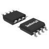
Part Details for ISL12025IBZ-T by Intersil Corporation
Results Overview of ISL12025IBZ-T by Intersil Corporation
- Distributor Offerings: (1 listing)
- Number of FFF Equivalents: (0 replacements)
- CAD Models: (Request Part)
- Number of Functional Equivalents: (0 options)
- Part Data Attributes: (Available)
- Reference Designs: (Not Available)
Tip: Data for a part may vary between manufacturers. You can filter for manufacturers on the top of the page next to the part image and part number.
ISL12025IBZ-T Information
ISL12025IBZ-T by Intersil Corporation is a Timer or RTC.
Timers or RTCs are under the broader part category of Microcontrollers and Processors.
Microcontrollers (MCUs) are small, low-power integrated circuits used to control embedded systems. Microcontrollers are primarily used to automate and control devices. Read more about Microcontrollers and Processors on our Microcontrollers and Processors part category page.
Price & Stock for ISL12025IBZ-T
| Part # | Distributor | Description | Stock | Price | Buy | |
|---|---|---|---|---|---|---|
|
|
Rochester Electronics | Real Time Clock, Non-Volatile, 0 Timer(s), CMOS, PDSO8 RoHS: Compliant Status: Obsolete Min Qty: 1 | 3 |
|
$3.0200 / $3.7700 | Buy Now |
Part Details for ISL12025IBZ-T
ISL12025IBZ-T CAD Models
ISL12025IBZ-T Part Data Attributes
|
|
ISL12025IBZ-T
Intersil Corporation
Buy Now
Datasheet
|
Compare Parts:
ISL12025IBZ-T
Intersil Corporation
Real-Time Clock/Calendar with I<sup>2</sup>C Bus™ and EEPROM; SOIC8, TSSOP8; Temp Range: -40° to 85°C
|
| Rohs Code | Yes | |
| Part Life Cycle Code | Obsolete | |
| Ihs Manufacturer | INTERSIL CORP | |
| Part Package Code | SOIC, TSSOP | |
| Package Description | ROHS COMPLIANT, PLASTIC, MS-012AA, SOIC-8 | |
| Pin Count | 8, 8 | |
| Reach Compliance Code | compliant | |
| ECCN Code | EAR99 | |
| HTS Code | 8542.39.00.01 | |
| Clock Frequency-Max | 0.032 MHz | |
| External Data Bus Width | ||
| Information Access Method | SERIAL(I2C) | |
| Interrupt Capability | Y | |
| JESD-30 Code | R-PDSO-G8 | |
| JESD-609 Code | e3 | |
| Length | 4.9 mm | |
| Moisture Sensitivity Level | 1 | |
| Number of Terminals | 8 | |
| Number of Timers | ||
| Operating Temperature-Max | 85 °C | |
| Operating Temperature-Min | -40 °C | |
| Package Body Material | PLASTIC/EPOXY | |
| Package Code | SOP | |
| Package Equivalence Code | SOP8,.25 | |
| Package Shape | RECTANGULAR | |
| Package Style | SMALL OUTLINE | |
| Peak Reflow Temperature (Cel) | 260 | |
| Qualification Status | Not Qualified | |
| Seated Height-Max | 1.75 mm | |
| Supply Voltage-Max | 5.5 V | |
| Supply Voltage-Min | 2.7 V | |
| Supply Voltage-Nom | 3.3 V | |
| Surface Mount | YES | |
| Technology | CMOS | |
| Temperature Grade | INDUSTRIAL | |
| Terminal Finish | MATTE TIN | |
| Terminal Form | GULL WING | |
| Terminal Pitch | 1.27 mm | |
| Terminal Position | DUAL | |
| Time-Min | SECONDS | |
| Time@Peak Reflow Temperature-Max (s) | 30 | |
| Volatile | NO | |
| Width | 3.9 mm | |
| uPs/uCs/Peripheral ICs Type | TIMER, REAL TIME CLOCK |
ISL12025IBZ-T Frequently Asked Questions (FAQ)
-
A good PCB layout for the ISL12025IBZ-T involves keeping the analog and digital grounds separate, using a solid ground plane, and minimizing the length of the clock signal traces. Additionally, it's recommended to place the device close to the crystal oscillator and to use a low-ESR capacitor for the VDD pin.
-
To ensure the accuracy of the clock output frequency, it's essential to use a high-quality crystal oscillator with a low ppm tolerance, and to follow the recommended crystal load capacitance values. Additionally, the device's internal clock trimming feature can be used to fine-tune the clock frequency.
-
The ISL12025IBZ-T can support clock frequencies up to 100MHz, but the maximum frequency may vary depending on the specific application and the quality of the crystal oscillator used.
-
The ISL12025IBZ-T can be configured for a specific clock output frequency by setting the appropriate values for the clock divider and multiplier registers. The device's datasheet provides a detailed explanation of the clock configuration process.
-
The power consumption of the ISL12025IBZ-T depends on the clock frequency, output load, and operating voltage. To minimize power consumption, it's recommended to use the lowest possible clock frequency, reduce the output load, and operate the device at the lowest possible voltage. Additionally, the device's power-down mode can be used to reduce power consumption when the device is not in use.
