-
Part Symbol
-
Footprint
-
3D Model
Available Download Formats
By downloading CAD models, you agree to our Terms & Conditions and Privacy Policy

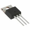
Power Field-Effect Transistor, 8.5A I(D), 650V, 0.93ohm, 1-Element, N-Channel, Silicon, Metal-oxide Semiconductor FET, TO-220AB, ROHS COMPLIANT PACKAGE-3
Tip: Data for a part may vary between manufacturers. You can filter for manufacturers on the top of the page next to the part image and part number.
IRFB9N65APBF by Vishay Intertechnologies is a Power Field-Effect Transistor.
Power Field-Effect Transistors are under the broader part category of Transistors.
A transistor is a small semiconductor device used to amplify, control, or create electrical signals. When selecting a transistor, factors such as voltage, current rating, gain, and power dissipation must be considered, with common types. Read more about Transistors on our Transistors part category page.
| Part # | Distributor | Description | Stock | Price | Buy | |
|---|---|---|---|---|---|---|
|
DISTI #
56AJ9864
|
Newark | Mosfet, N-Ch, 650 V, 8.5 A, To-220-3, Channel Type:N Channel, Drain Source Voltage Vds:650V, Continuous Drain Current Id:8.5A, Transistor Mounting:Through Hole, Rds(On) Test Voltage:10V, Gate Source Threshold Voltage Max:4V Rohs Compliant: Yes |Vishay IRFB9N65APBF RoHS: Compliant Min Qty: 1 Package Multiple: 1 Date Code: 0 Container: Bulk | 2 |
|
$1.9200 / $3.1600 | Buy Now |
|
|
Bristol Electronics | 4300 |
|
RFQ | ||
|
DISTI #
IRFB9N65APBF
|
TME | Transistor: N-MOSFET, unipolar, 650V, 5.4A, 167W, TO220AB Min Qty: 1 | 0 |
|
$0.9200 / $1.3700 | RFQ |
|
|
ComSIT USA | POWER MOSFET Power Field-Effect Transistor, 8.5A I(D), 650V, 0.93ohm, 1-Element, N-Channel, Silicon, Metal-oxide Semiconductor FET, TO-220AB ECCN: EAR99 RoHS: Compliant |
|
|
RFQ | |
|
DISTI #
IRFB9N65APBF
|
EBV Elektronik | MOSFET NCHANNEL 650V (Alt: IRFB9N65APBF) RoHS: Compliant Min Qty: 50 Package Multiple: 50 Lead time: 143 Weeks, 0 Days | EBV - 0 |
|
Buy Now | |
|
|
LCSC | 650V 5.4A 930m10V5.1A 167W 2V 1 N-channel TO-220AB MOSFETs ROHS | 8 |
|
$1.9523 / $2.0564 | Buy Now |
By downloading CAD models, you agree to our Terms & Conditions and Privacy Policy
|
|
IRFB9N65APBF
Vishay Intertechnologies
Buy Now
Datasheet
|
Compare Parts:
IRFB9N65APBF
Vishay Intertechnologies
Power Field-Effect Transistor, 8.5A I(D), 650V, 0.93ohm, 1-Element, N-Channel, Silicon, Metal-oxide Semiconductor FET, TO-220AB, ROHS COMPLIANT PACKAGE-3
|
| Pbfree Code | Yes | |
| Rohs Code | Yes | |
| Part Life Cycle Code | Obsolete | |
| Ihs Manufacturer | VISHAY INTERTECHNOLOGY INC | |
| Part Package Code | TO-220AB | |
| Pin Count | 3 | |
| Reach Compliance Code | compliant | |
| ECCN Code | EAR99 | |
| Samacsys Manufacturer | Vishay | |
| Avalanche Energy Rating (Eas) | 325 mJ | |
| Case Connection | DRAIN | |
| Configuration | SINGLE WITH BUILT-IN DIODE | |
| DS Breakdown Voltage-Min | 650 V | |
| Drain Current-Max (ID) | 8.5 A | |
| Drain-source On Resistance-Max | 0.93 Ω | |
| FET Technology | METAL-OXIDE SEMICONDUCTOR | |
| JEDEC-95 Code | TO-220AB | |
| JESD-30 Code | R-PSFM-T3 | |
| JESD-609 Code | e3 | |
| Number of Elements | 1 | |
| Number of Terminals | 3 | |
| Operating Mode | ENHANCEMENT MODE | |
| Operating Temperature-Max | 150 °C | |
| Package Body Material | PLASTIC/EPOXY | |
| Package Shape | RECTANGULAR | |
| Package Style | FLANGE MOUNT | |
| Peak Reflow Temperature (Cel) | 260 | |
| Polarity/Channel Type | N-CHANNEL | |
| Power Dissipation-Max (Abs) | 167 W | |
| Pulsed Drain Current-Max (IDM) | 21 A | |
| Qualification Status | Not Qualified | |
| Surface Mount | NO | |
| Terminal Finish | Matte Tin (Sn) | |
| Terminal Form | THROUGH-HOLE | |
| Terminal Position | SINGLE | |
| Time@Peak Reflow Temperature-Max (s) | 30 | |
| Transistor Application | SWITCHING | |
| Transistor Element Material | SILICON |
The maximum SOA for the IRFB9N65APBF is typically defined by the manufacturer as the region where the device can operate safely without damage. This information is usually provided in the datasheet or in a separate application note. For the IRFB9N65APBF, the SOA is typically limited by the maximum drain-source voltage (Vds) and drain current (Id).
To ensure the IRFB9N65APBF is fully turned on and off, you should provide a sufficient gate-source voltage (Vgs) and a fast enough switching time. The recommended Vgs is typically around 10V for this device. Additionally, the gate driver should be capable of providing a high current (e.g., 1A) to quickly charge and discharge the gate capacitance.
The thermal resistance (Rth) of the IRFB9N65APBF is typically around 0.5°C/W (junction-to-case) and 62°C/W (case-to-ambient). This means that for every watt of power dissipated, the junction temperature will increase by 0.5°C. To ensure reliable operation, it's essential to keep the junction temperature below the maximum rated value (150°C for this device).
The IRFB9N65APBF is suitable for high-frequency switching applications due to its low gate charge (Qg) and internal gate resistance (Rg). However, the maximum switching frequency is limited by the device's parasitic capacitances and the gate driver's capabilities. A good rule of thumb is to keep the switching frequency below 100 kHz to minimize power losses and ensure reliable operation.
To protect the IRFB9N65APBF from overvoltage and overcurrent conditions, you can use a combination of voltage clamping devices (e.g., zener diodes or TVS diodes) and current sensing resistors. Additionally, consider using a gate driver with built-in overcurrent protection and undervoltage lockout (UVLO) features.