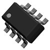
Part Details for IRF9310PBF by International Rectifier
Results Overview of IRF9310PBF by International Rectifier
- Distributor Offerings: (0 listings)
- Number of FFF Equivalents: (0 replacements)
- CAD Models: (Request Part)
- Number of Functional Equivalents: (0 options)
- Part Data Attributes: (Available)
- Reference Designs: (Not Available)
Tip: Data for a part may vary between manufacturers. You can filter for manufacturers on the top of the page next to the part image and part number.
IRF9310PBF Information
IRF9310PBF by International Rectifier is a Small Signal Field-Effect Transistor.
Small Signal Field-Effect Transistors are under the broader part category of Transistors.
A transistor is a small semiconductor device used to amplify, control, or create electrical signals. When selecting a transistor, factors such as voltage, current rating, gain, and power dissipation must be considered, with common types. Read more about Transistors on our Transistors part category page.
Part Details for IRF9310PBF
IRF9310PBF CAD Models
IRF9310PBF Part Data Attributes
|
|
IRF9310PBF
International Rectifier
Buy Now
Datasheet
|
Compare Parts:
IRF9310PBF
International Rectifier
Power Field-Effect Transistor, 20A I(D), 30V, 0.0046ohm, 1-Element, P-Channel, Silicon, Metal-oxide Semiconductor FET, HALOGEN FREE AND ROHS COMPLIANT, SOP-8
|
| Pbfree Code | Yes | |
| Rohs Code | Yes | |
| Part Life Cycle Code | Transferred | |
| Ihs Manufacturer | INTERNATIONAL RECTIFIER CORP | |
| Part Package Code | SOT | |
| Package Description | SOP-8 | |
| Pin Count | 8 | |
| Reach Compliance Code | compliant | |
| ECCN Code | EAR99 | |
| Avalanche Energy Rating (Eas) | 630 mJ | |
| Configuration | SINGLE WITH BUILT-IN DIODE | |
| DS Breakdown Voltage-Min | 30 V | |
| Drain Current-Max (ID) | 20 A | |
| Drain-source On Resistance-Max | 0.0046 Ω | |
| FET Technology | METAL-OXIDE SEMICONDUCTOR | |
| Feedback Cap-Max (Crss) | 880 pF | |
| JEDEC-95 Code | MS-012AA | |
| JESD-30 Code | R-PDSO-G8 | |
| JESD-609 Code | e3 | |
| Moisture Sensitivity Level | 1 | |
| Number of Elements | 1 | |
| Number of Terminals | 8 | |
| Operating Mode | ENHANCEMENT MODE | |
| Operating Temperature-Max | 150 °C | |
| Operating Temperature-Min | -55 °C | |
| Package Body Material | PLASTIC/EPOXY | |
| Package Shape | RECTANGULAR | |
| Package Style | SMALL OUTLINE | |
| Polarity/Channel Type | P-CHANNEL | |
| Power Dissipation-Max (Abs) | 2.5 W | |
| Pulsed Drain Current-Max (IDM) | 160 A | |
| Qualification Status | Not Qualified | |
| Surface Mount | YES | |
| Terminal Finish | MATTE TIN | |
| Terminal Form | GULL WING | |
| Terminal Position | DUAL | |
| Transistor Application | SWITCHING | |
| Transistor Element Material | SILICON |
IRF9310PBF Frequently Asked Questions (FAQ)
-
The maximum operating temperature range for the IRF9310PBF is -55°C to 175°C.
-
Yes, the IRF9310PBF is suitable for high-frequency switching applications up to 1 MHz, but it's essential to consider the device's switching losses and thermal management.
-
To ensure proper biasing, apply a gate-source voltage (Vgs) between 4V to 10V, and maintain a drain-source voltage (Vds) within the recommended range of 20V to 100V.
-
The recommended gate resistor value for the IRF9310PBF is typically between 10Ω to 100Ω, depending on the specific application and switching frequency.
-
No, the IRF9310PBF is not suitable for linear amplifier applications due to its high power MOSFET characteristics, which are optimized for switching applications.
