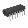
Part Details for IR2110L4SCS by International Rectifier
Results Overview of IR2110L4SCS by International Rectifier
- Distributor Offerings: (1 listing)
- Number of FFF Equivalents: (0 replacements)
- CAD Models: (Request Part)
- Number of Functional Equivalents: (0 options)
- Part Data Attributes: (Available)
- Reference Designs: (Not Available)
Tip: Data for a part may vary between manufacturers. You can filter for manufacturers on the top of the page next to the part image and part number.
IR2110L4SCS Information
IR2110L4SCS by International Rectifier is an MOSFET Driver.
MOSFET Drivers are under the broader part category of Drivers And Interfaces.
A driver controls the current or voltage delivered to components like LCDs or motors, while an interface component connects systems for data transfer and control. Read more about Drivers And Interfaces on our Drivers And Interfaces part category page.
Price & Stock for IR2110L4SCS
| Part # | Distributor | Description | Stock | Price | Buy | |
|---|---|---|---|---|---|---|
|
|
Vyrian | Interface ICs | 967 |
|
RFQ |
Part Details for IR2110L4SCS
IR2110L4SCS CAD Models
IR2110L4SCS Part Data Attributes
|
|
IR2110L4SCS
International Rectifier
Buy Now
Datasheet
|
Compare Parts:
IR2110L4SCS
International Rectifier
Half Bridge Based MOSFET Driver, 2A, CMOS, CDIP14, MO-036AB, 14 PIN
|
| Pbfree Code | No | |
| Rohs Code | No | |
| Part Life Cycle Code | Transferred | |
| Ihs Manufacturer | INTERNATIONAL RECTIFIER CORP | |
| Part Package Code | DIP | |
| Package Description | MO-036AB, 14 PIN | |
| Pin Count | 14 | |
| Reach Compliance Code | compliant | |
| ECCN Code | EAR99 | |
| HTS Code | 8542.39.00.01 | |
| High Side Driver | YES | |
| Interface IC Type | HALF BRIDGE BASED MOSFET DRIVER | |
| JESD-30 Code | R-CDIP-T14 | |
| JESD-609 Code | e0 | |
| Length | 19 mm | |
| Number of Functions | 1 | |
| Number of Terminals | 14 | |
| Output Peak Current Limit-Nom | 2 A | |
| Package Body Material | CERAMIC, METAL-SEALED COFIRED | |
| Package Code | DIP | |
| Package Equivalence Code | DIP14,.3 | |
| Package Shape | RECTANGULAR | |
| Package Style | IN-LINE | |
| Qualification Status | Not Qualified | |
| Screening Level | MIL-STD-883 Class S | |
| Seated Height-Max | 4.44 mm | |
| Supply Voltage-Max | 20 V | |
| Supply Voltage-Min | 5 V | |
| Supply Voltage-Nom | 15 V | |
| Supply Voltage1-Max | 420 V | |
| Supply Voltage1-Min | 6 V | |
| Supply Voltage1-Nom | 15 V | |
| Surface Mount | NO | |
| Technology | CMOS | |
| Terminal Finish | TIN LEAD | |
| Terminal Form | THROUGH-HOLE | |
| Terminal Pitch | 2.54 mm | |
| Terminal Position | DUAL | |
| Turn-off Time | 220 µs | |
| Turn-on Time | 260 µs | |
| Width | 7.62 mm |
IR2110L4SCS Frequently Asked Questions (FAQ)
-
The maximum voltage rating of the IR2110L4SCS is 500V, but it can be used in applications up to 600V with proper design and layout considerations.
-
Proper thermal management can be achieved by providing a heat sink with a thermal resistance of less than 10°C/W, and ensuring good airflow around the device. Additionally, the PCB layout should be designed to minimize thermal resistance.
-
The recommended dead time for the IR2110L4SCS is typically around 100-200ns, but this can vary depending on the specific application and switching frequency.
-
Overcurrent protection can be achieved using a current sense resistor and a comparator, while overvoltage protection can be achieved using a voltage monitor IC and a comparator. Additionally, a fuse or a PTC can be used to provide additional protection.
-
The recommended layout and routing for the IR2110L4SCS involves keeping the high-voltage and low-voltage sections separate, using a star-point grounding scheme, and minimizing the length of the high-voltage traces.
