-
Part Symbol
-
Footprint
-
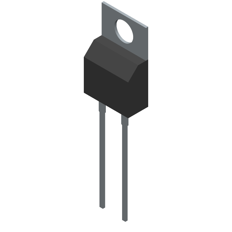
3D Model
Available Download Formats
By downloading CAD models, you agree to our Terms & Conditions and Privacy Policy

Rectifier Diode, 1 Phase, 1 Element, 71A, 600V V(RRM), Silicon, TO-220AC, GREEN, PLASTIC, TO-220, 2 PIN
Tip: Data for a part may vary between manufacturers. You can filter for manufacturers on the top of the page next to the part image and part number.
IDP45E60XKSA1 by Infineon Technologies AG is a Rectifier Diode.
Rectifier Diodes are under the broader part category of Diodes.
A diode is a electrical part that can control the direction in which the current flows in a device. Consider factors like voltage drop, current capacity, reverse voltage, and operating frequency when selecting a diode. Read more about Diodes on our Diodes part category page.
| Part # | Distributor | Description | Stock | Price | Buy | |
|---|---|---|---|---|---|---|
|
DISTI #
SP000683034
|
EBV Elektronik | Diode 600V 45A 2Pin TO220 (Alt: SP000683034) RoHS: Compliant Min Qty: 500 Package Multiple: 500 Lead time: 143 Weeks, 0 Days | EBV - 0 |
|
Buy Now | |
|
|
Vyrian | Diodes | 83 |
|
RFQ |
By downloading CAD models, you agree to our Terms & Conditions and Privacy Policy
|
|
IDP45E60XKSA1
Infineon Technologies AG
Buy Now
Datasheet
|
Compare Parts:
IDP45E60XKSA1
Infineon Technologies AG
Rectifier Diode, 1 Phase, 1 Element, 71A, 600V V(RRM), Silicon, TO-220AC, GREEN, PLASTIC, TO-220, 2 PIN
|
| Pbfree Code | Yes | |
| Rohs Code | Yes | |
| Part Life Cycle Code | Obsolete | |
| Ihs Manufacturer | INFINEON TECHNOLOGIES AG | |
| Part Package Code | TO-220AC | |
| Package Description | GREEN, PLASTIC, TO-220, 2 PIN | |
| Pin Count | 3 | |
| Reach Compliance Code | compliant | |
| ECCN Code | EAR99 | |
| HTS Code | 8541.10.00.80 | |
| Samacsys Manufacturer | Infineon | |
| Application | FAST SOFT RECOVERY | |
| Case Connection | CATHODE | |
| Configuration | SINGLE | |
| Diode Element Material | SILICON | |
| Diode Type | RECTIFIER DIODE | |
| JEDEC-95 Code | TO-220AC | |
| JESD-30 Code | R-PSFM-T2 | |
| JESD-609 Code | e3 | |
| Non-rep Pk Forward Current-Max | 162 A | |
| Number of Elements | 1 | |
| Number of Phases | 1 | |
| Number of Terminals | 2 | |
| Operating Temperature-Max | 175 °C | |
| Operating Temperature-Min | -55 °C | |
| Output Current-Max | 71 A | |
| Package Body Material | PLASTIC/EPOXY | |
| Package Shape | RECTANGULAR | |
| Package Style | FLANGE MOUNT | |
| Power Dissipation-Max | 187 W | |
| Qualification Status | Not Qualified | |
| Rep Pk Reverse Voltage-Max | 600 V | |
| Reverse Recovery Time-Max | 0.14 µs | |
| Surface Mount | NO | |
| Terminal Finish | Tin (Sn) | |
| Terminal Form | THROUGH-HOLE | |
| Terminal Position | SINGLE |
A 2-layer or 4-layer PCB with a large copper area for heat dissipation is recommended. The device should be placed near a heat sink or a metal plate for optimal thermal performance.
Ensure proper heat sinking, use a thermal interface material, and follow the recommended PCB layout guidelines. Also, consider using a thermocouple or thermistor to monitor the device temperature.
Monitor the drain-source voltage, gate-source voltage, and drain current to ensure the device is operating within the recommended specifications.
Use a voltage regulator or a voltage limiter to prevent overvoltage. Implement overcurrent protection using a current sense resistor and a comparator or a dedicated overcurrent protection IC.
Use a dedicated gate driver IC or a discrete gate drive circuit with a low impedance output stage to ensure fast switching times and minimal ringing.