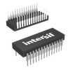
Part Details for ICM7218BIJIR5254 by Intersil Corporation
Results Overview of ICM7218BIJIR5254 by Intersil Corporation
- Distributor Offerings: (1 listing)
- Number of FFF Equivalents: (0 replacements)
- CAD Models: (Request Part)
- Number of Functional Equivalents: (0 options)
- Part Data Attributes: (Available)
- Reference Designs: (Not Available)
Tip: Data for a part may vary between manufacturers. You can filter for manufacturers on the top of the page next to the part image and part number.
ICM7218BIJIR5254 Information
ICM7218BIJIR5254 by Intersil Corporation is a Display Driver.
Display Drivers are under the broader part category of Drivers And Interfaces.
A driver controls the current or voltage delivered to components like LCDs or motors, while an interface component connects systems for data transfer and control. Read more about Drivers And Interfaces on our Drivers And Interfaces part category page.
Price & Stock for ICM7218BIJIR5254
| Part # | Distributor | Description | Stock | Price | Buy | |
|---|---|---|---|---|---|---|
|
|
Vyrian | Interface ICs | 285 |
|
RFQ |
Part Details for ICM7218BIJIR5254
ICM7218BIJIR5254 CAD Models
ICM7218BIJIR5254 Part Data Attributes
|
|
ICM7218BIJIR5254
Intersil Corporation
Buy Now
Datasheet
|
Compare Parts:
ICM7218BIJIR5254
Intersil Corporation
8-Digit LED Microprocessor-Compatible Multiplexed Display Decoder Driver; CERDIP28; Temp Range: -40° to 85°C
|
| Rohs Code | Yes | |
| Part Life Cycle Code | Transferred | |
| Ihs Manufacturer | INTERSIL CORP | |
| Part Package Code | CERDIP | |
| Package Description | CERAMIC, DIP-28 | |
| Pin Count | 28 | |
| Reach Compliance Code | compliant | |
| ECCN Code | EAR99 | |
| HTS Code | 8542.39.00.01 | |
| Factory Lead Time | 26 Weeks | |
| Additional Feature | ONE DECIMAL POINT OUTPUT | |
| Data Input Mode | PARALLEL | |
| Display Mode | SEGMENT | |
| Interface IC Type | LED DISPLAY DRIVER | |
| JESD-30 Code | R-GDIP-T28 | |
| JESD-609 Code | e3 | |
| Multiplexed Display Capability | YES | |
| Number of Digits/Characters | 8-DIGIT | |
| Number of Functions | 1 | |
| Number of Segments | 8 | |
| Number of Terminals | 28 | |
| Operating Temperature-Max | 85 °C | |
| Operating Temperature-Min | -40 °C | |
| Package Body Material | CERAMIC, GLASS-SEALED | |
| Package Code | DIP | |
| Package Equivalence Code | DIP28,.6 | |
| Package Shape | RECTANGULAR | |
| Package Style | IN-LINE | |
| Qualification Status | Not Qualified | |
| Seated Height-Max | 5.92 mm | |
| Supply Voltage-Max | 6 V | |
| Supply Voltage-Min | 4 V | |
| Supply Voltage-Nom | 5 V | |
| Surface Mount | NO | |
| Technology | CMOS | |
| Temperature Grade | INDUSTRIAL | |
| Terminal Finish | MATTE TIN | |
| Terminal Form | THROUGH-HOLE | |
| Terminal Pitch | 2.54 mm | |
| Terminal Position | DUAL | |
| Width | 15.24 mm |
ICM7218BIJIR5254 Frequently Asked Questions (FAQ)
-
A good layout and routing practice is to keep the analog and digital grounds separate, use a solid ground plane, and keep the power supply lines away from the analog signals. Additionally, use a low-ESR capacitor for decoupling and place it close to the VCC pin.
-
Make sure to follow the power-up sequence specified in the datasheet, which is VCC first, then VDD. Also, ensure that the voltage supply is stable and within the recommended range. Initialize the device by setting the CS pin high and then low to enable the internal oscillator.
-
The maximum clock frequency is 40 MHz, but it's recommended to use a clock frequency of 32 kHz or less for optimal performance and to minimize power consumption.
-
To enter power-down mode, set the PD pin high. In this mode, the device consumes minimal power, but the internal oscillator is disabled. To exit power-down mode, set the PD pin low and wait for the internal oscillator to stabilize before accessing the device.
-
Use a SPI master device to communicate with the ICM7218BIJIR5254. Ensure that the CS pin is asserted low before transmitting data, and de-assert it high after transmission. Use a clock frequency of 1 MHz or less, and ensure that the data is transmitted MSB-first.
