-
Part Symbol
-
Footprint
-
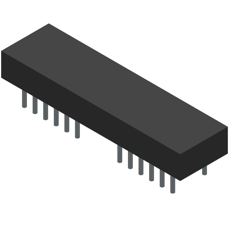
3D Model
Available Download Formats
By downloading CAD models, you agree to our Terms & Conditions and Privacy Policy
5X7 DOT MATRIX DISPLAY, GREEN, 4.57mm, DIP-30
Tip: Data for a part may vary between manufacturers. You can filter for manufacturers on the top of the page next to the part image and part number.
HDSP-2533 by Avago Technologies is an LED Display.
LED Displays are under the broader part category of Optoelectronics.
Optoelectronic components work to detect, generate, and control light. They can essentially produce and/or react to light. Read more about Optoelectronics on our Optoelectronics part category page.
| Part # | Manufacturer | Description | Datasheet |
|---|---|---|---|
| RJE1R288225332 | Amphenol Communications Solutions | Modular Jack - 8P8C, RA, Cat5e, Stacked, 2x1 Two Port, Shield With Top and Side EMI Tabs, With LEDs | |
| RJE1R288225331 | Amphenol Communications Solutions | Modular Jack - 8P8C, RA, Cat5e, Stacked, 2x1 Two Port, Shield With Top and Side EMI Tabs, With LEDs | |
| G97V25332HR | Amphenol Communications Solutions | Mini Cool Edge IO(MCIO), SFF-TA-1016, PCIe Gen 5, 85Ω, Surfacemount, Vertical, 50 Pin, PCIe, SAS, SFP, NVMe, cable, dual, card. |
| Part # | Distributor | Description | Stock | Price | Buy | |
|---|---|---|---|---|---|---|
|
DISTI #
70157868
|
RS | 5X7 SMARTDISP 8CHAR .18IN, GRN Min Qty: 1 Package Multiple: 1 Container: Bulk | 0 |
|
$28.3700 / $35.5400 | RFQ |
By downloading CAD models, you agree to our Terms & Conditions and Privacy Policy
|
|
HDSP-2533
Avago Technologies
Buy Now
Datasheet
|
Compare Parts:
HDSP-2533
Avago Technologies
5X7 DOT MATRIX DISPLAY, GREEN, 4.57mm, DIP-30
|
| Pbfree Code | Yes | |
| Rohs Code | Yes | |
| Part Life Cycle Code | Active | |
| Ihs Manufacturer | AVAGO TECHNOLOGIES INC | |
| Package Description | DIP-30 | |
| Reach Compliance Code | compliant | |
| HTS Code | 8541.40.20.00 | |
| Samacsys Manufacturer | Avago Technologies | |
| Additional Feature | TTL COMPATIBLE | |
| Color | GREEN | |
| Color@Wavelength | Green | |
| Configuration | COMPLEX | |
| Display Height | 4.57 mm | |
| JESD-609 Code | e2 | |
| Number of Characters | 8 | |
| Number of Functions | 8 | |
| Operating Temperature-Max | 85 °C | |
| Operating Temperature-Min | -40 °C | |
| Optoelectronic Device Type | 5 X 7 DOT MATRIX LED DISPLAY | |
| Peak Wavelength | 568 nm | |
| Terminal Finish | TIN COPPER |
This table gives cross-reference parts and alternative options found for HDSP-2533. The Form Fit Function (FFF) tab will give you the options that are more likely to serve as direct pin-to-pin alternates or drop-in parts. The Functional Equivalents tab will give you options that are likely to match the same function of HDSP-2533, but it may not fit your design. Always verify details of parts you are evaluating, as these parts are offered as suggestions for what you are looking for and are not guaranteed.
| Part Number | Manufacturer | Composite Price | Description | Compare |
|---|---|---|---|---|
| HDSP-2533 | Hewlett Packard Co | Check for Price | Smart/Normal 5 X 7 Dot Matrix LED Display, 8-Character, Green, 5mm | HDSP-2533 vs HDSP-2533 |
Broadcom provides a recommended PCB layout guide for the HDSP-2533, which includes guidelines for component placement, routing, and thermal management. It's essential to follow this guide to ensure optimal performance and reliability.
To optimize the HDSP-2533 for low power consumption, ensure that the device is operated within the recommended voltage range, use the power-down mode when not in use, and optimize the clock frequency and data rate. Additionally, consider using a low-power mode or dynamic voltage and frequency scaling (DVFS) to reduce power consumption.
The HDSP-2533 has a maximum junction temperature of 125°C. To ensure reliable operation, it's essential to provide adequate thermal management, such as using a heat sink, thermal interface material, and ensuring good airflow around the device.
To troubleshoot issues with the HDSP-2533, start by reviewing the datasheet and application notes, checking the device's configuration and programming, and verifying the power supply and clock signals. Use debugging tools, such as logic analyzers or oscilloscopes, to identify and isolate the issue.
To minimize electromagnetic interference (EMI) and radio-frequency interference (RFI) with the HDSP-2533, follow proper PCB design and layout guidelines, use shielding and grounding techniques, and ensure that the device is operated within the recommended frequency range.