-
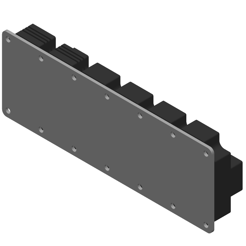
3D Model
Available Download Formats
By downloading CAD models, you agree to our Terms & Conditions and Privacy Policy
Insulated Gate Bipolar Transistor, 1400A I(C), 1200V V(BR)CES, N-Channel, MODULE-13
Tip: Data for a part may vary between manufacturers. You can filter for manufacturers on the top of the page next to the part image and part number.
FF1400R12IP4 by Infineon Technologies AG is an IGBT.
IGBTs are under the broader part category of Transistors.
A transistor is a small semiconductor device used to amplify, control, or create electrical signals. When selecting a transistor, factors such as voltage, current rating, gain, and power dissipation must be considered, with common types. Read more about Transistors on our Transistors part category page.
| Part # | Distributor | Description | Stock | Price | Buy | |
|---|---|---|---|---|---|---|
|
DISTI #
641-FF1400R12IP4
|
Mouser Electronics | IGBT Modules 1200 V, 1400 A dual IGBT module RoHS: Compliant | 0 |
|
$634.5500 / $634.5600 | Order Now |
|
|
MacroQuest Electronics | 46 |
|
RFQ | ||
|
|
Win Source Electronics | PrimePACK™3 Modul mit Trench/Fieldstopp IGBT4 und Emitter Controlled 4 Diode und NTC | 1052 |
|
$396.2292 | Buy Now |
By downloading CAD models, you agree to our Terms & Conditions and Privacy Policy
|
|
FF1400R12IP4
Infineon Technologies AG
Buy Now
Datasheet
|
Compare Parts:
FF1400R12IP4
Infineon Technologies AG
Insulated Gate Bipolar Transistor, 1400A I(C), 1200V V(BR)CES, N-Channel, MODULE-13
|
| Pbfree Code | Yes | |
| Rohs Code | Yes | |
| Part Life Cycle Code | Active | |
| Ihs Manufacturer | INFINEON TECHNOLOGIES AG | |
| Part Package Code | MODULE | |
| Package Description | MODULE-13 | |
| Pin Count | 13 | |
| Reach Compliance Code | compliant | |
| ECCN Code | EAR99 | |
| Samacsys Manufacturer | Infineon | |
| Case Connection | ISOLATED | |
| Collector Current-Max (IC) | 1400 A | |
| Collector-Emitter Voltage-Max | 1200 V | |
| Configuration | SERIES CONNECTED, CENTER TAP, 2 ELEMENTS WITH BUILT-IN DIODE AND THERMISTOR | |
| Gate-Emitter Voltage-Max | 20 V | |
| JESD-30 Code | R-XUFM-X7 | |
| Number of Elements | 2 | |
| Number of Terminals | 7 | |
| Operating Temperature-Max | 175 °C | |
| Package Body Material | UNSPECIFIED | |
| Package Shape | RECTANGULAR | |
| Package Style | FLANGE MOUNT | |
| Peak Reflow Temperature (Cel) | NOT SPECIFIED | |
| Polarity/Channel Type | N-CHANNEL | |
| Power Dissipation-Max (Abs) | 7600 W | |
| Qualification Status | Not Qualified | |
| Surface Mount | NO | |
| Terminal Form | UNSPECIFIED | |
| Terminal Position | UPPER | |
| Time@Peak Reflow Temperature-Max (s) | NOT SPECIFIED | |
| Transistor Application | POWER CONTROL | |
| Transistor Element Material | SILICON | |
| Turn-off Time-Nom (toff) | 1200 ns | |
| Turn-on Time-Nom (ton) | 340 ns | |
| VCEsat-Max | 2.05 V |
The maximum junction temperature of the FF1400R12IP4 is 150°C, as specified in the datasheet. However, it's recommended to operate the device at a temperature below 125°C for optimal performance and reliability.
To ensure reliability, it's essential to follow proper thermal management practices, such as providing adequate heat sinking and ensuring good airflow around the device. Additionally, operating the device within its specified ratings and avoiding overheating can help prevent premature failure.
The recommended gate drive voltage for the FF1400R12IP4 is between 10V and 15V. However, it's essential to consult the datasheet and application notes for specific guidance on gate drive voltage and current requirements.
Yes, the FF1400R12IP4 can be used in a parallel configuration to increase power handling. However, it's crucial to ensure that the devices are properly matched and that the gate drive signals are synchronized to prevent uneven current sharing and potential damage to the devices.
The maximum allowable voltage transient for the FF1400R12IP4 is specified in the datasheet as 1200V. However, it's essential to consult the datasheet and application notes for specific guidance on voltage transient protection and overvoltage protection circuits.