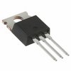
Part Details for DSA60C150PB by IXYS Corporation
Results Overview of DSA60C150PB by IXYS Corporation
- Distributor Offerings: (2 listings)
- Number of FFF Equivalents: (0 replacements)
- CAD Models: (Request Part)
- Number of Functional Equivalents: (0 options)
- Part Data Attributes: (Available)
- Reference Designs: (Not Available)
Tip: Data for a part may vary between manufacturers. You can filter for manufacturers on the top of the page next to the part image and part number.
DSA60C150PB Information
DSA60C150PB by IXYS Corporation is a Rectifier Diode.
Rectifier Diodes are under the broader part category of Diodes.
A diode is a electrical part that can control the direction in which the current flows in a device. Consider factors like voltage drop, current capacity, reverse voltage, and operating frequency when selecting a diode. Read more about Diodes on our Diodes part category page.
Price & Stock for DSA60C150PB
| Part # | Distributor | Description | Stock | Price | Buy | |
|---|---|---|---|---|---|---|
|
DISTI #
DSA60C150PB-ND
|
DigiKey | DIODE ARR SCHOT 150V 30A TO2203 Min Qty: 8000 Lead time: 15 Weeks Container: Tube | Temporarily Out of Stock |
|
$1.3381 | Buy Now |
|
DISTI #
DSA60C150PB
|
TTI | Schottky Diodes & Rectifiers Schottky Diode Gen2 Min Qty: 8000 Package Multiple: 50 Container: Tube | Americas - 0 |
|
$1.3100 / $1.3300 | Buy Now |
Part Details for DSA60C150PB
DSA60C150PB CAD Models
DSA60C150PB Part Data Attributes
|
|
DSA60C150PB
IXYS Corporation
Buy Now
Datasheet
|
Compare Parts:
DSA60C150PB
IXYS Corporation
Rectifier Diode, Schottky, 1 Phase, 2 Element, 30A, 150V V(RRM), Silicon, TO-220AB, ROHS COMPLIANT, PLASTIC PACKAGE-3
|
| Pbfree Code | Yes | |
| Rohs Code | Yes | |
| Part Life Cycle Code | Transferred | |
| Ihs Manufacturer | IXYS CORP | |
| Part Package Code | TO-220AB | |
| Package Description | ROHS COMPLIANT, PLASTIC PACKAGE-3 | |
| Pin Count | 3 | |
| Reach Compliance Code | compliant | |
| ECCN Code | EAR99 | |
| HTS Code | 8541.10.00.80 | |
| Additional Feature | FREE WHEELING DIODE, HIGH RELIABILITY, LOW NOISE | |
| Application | SOFT RECOVERY | |
| Case Connection | CATHODE | |
| Configuration | COMMON CATHODE, 2 ELEMENTS | |
| Diode Element Material | SILICON | |
| Diode Type | RECTIFIER DIODE | |
| Forward Voltage-Max (VF) | 0.8 V | |
| JEDEC-95 Code | TO-220AB | |
| JESD-30 Code | R-PSFM-T3 | |
| Non-rep Pk Forward Current-Max | 200 A | |
| Number of Elements | 2 | |
| Number of Phases | 1 | |
| Number of Terminals | 3 | |
| Operating Temperature-Max | 175 °C | |
| Operating Temperature-Min | -55 °C | |
| Output Current-Max | 30 A | |
| Package Body Material | PLASTIC/EPOXY | |
| Package Shape | RECTANGULAR | |
| Package Style | FLANGE MOUNT | |
| Peak Reflow Temperature (Cel) | NOT SPECIFIED | |
| Qualification Status | Not Qualified | |
| Rep Pk Reverse Voltage-Max | 150 V | |
| Surface Mount | NO | |
| Technology | SCHOTTKY | |
| Terminal Form | THROUGH-HOLE | |
| Terminal Position | SINGLE | |
| Time@Peak Reflow Temperature-Max (s) | NOT SPECIFIED |
DSA60C150PB Frequently Asked Questions (FAQ)
-
The recommended gate drive voltage for the DSA60C150PB is between 10V to 15V, with a typical value of 12V. This ensures proper switching and minimizes losses.
-
To ensure SOA compliance, the device should be operated within the specified voltage and current ratings. Additionally, the user should ensure that the device is not subjected to excessive voltage or current transients, and that the thermal management is adequate to prevent overheating.
-
The maximum allowed case temperature for the DSA60C150PB is 150°C. Exceeding this temperature can lead to reduced performance, reliability issues, and even device failure.
-
Yes, the DSA60C150PB can be used in a parallel configuration to increase the overall current handling capability. However, it is essential to ensure that the devices are properly matched, and the gate drive signals are synchronized to prevent uneven current sharing.
-
A good PCB layout should ensure minimal inductance and resistance in the power paths, and adequate thermal management should be implemented to prevent overheating. A heat sink with a thermal resistance of less than 1°C/W is recommended, and the device should be mounted using a suitable thermal interface material.
