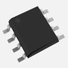
Part Details for DS75453M by Texas Instruments
Results Overview of DS75453M by Texas Instruments
- Distributor Offerings: (0 listings)
- Number of FFF Equivalents: (0 replacements)
- CAD Models: (Request Part)
- Number of Functional Equivalents: (1 option)
- Part Data Attributes: (Available)
- Reference Designs: (Not Available)
Tip: Data for a part may vary between manufacturers. You can filter for manufacturers on the top of the page next to the part image and part number.
DS75453M Information
DS75453M by Texas Instruments is a Peripheral Driver.
Peripheral Drivers are under the broader part category of Drivers And Interfaces.
A driver controls the current or voltage delivered to components like LCDs or motors, while an interface component connects systems for data transfer and control. Read more about Drivers And Interfaces on our Drivers And Interfaces part category page.
Part Details for DS75453M
DS75453M CAD Models
DS75453M Part Data Attributes
|
|
DS75453M
Texas Instruments
Buy Now
Datasheet
|
Compare Parts:
DS75453M
Texas Instruments
OR GATE BASED PRPHL DRVR
|
| Part Life Cycle Code | Obsolete | |
| Ihs Manufacturer | TEXAS INSTRUMENTS INC | |
| Part Package Code | SOIC | |
| Package Description | SOP, | |
| Pin Count | 8 | |
| Reach Compliance Code | unknown | |
| ECCN Code | EAR99 | |
| HTS Code | 8542.39.00.01 | |
| Interface IC Type | OR GATE BASED PERIPHERAL DRIVER | |
| JESD-30 Code | R-PDSO-G8 | |
| Length | 4.902 mm | |
| Number of Functions | 2 | |
| Number of Terminals | 8 | |
| Operating Temperature-Max | 70 °C | |
| Operating Temperature-Min | ||
| Output Current Flow Direction | SINK | |
| Package Body Material | PLASTIC/EPOXY | |
| Package Code | SOP | |
| Package Shape | RECTANGULAR | |
| Package Style | SMALL OUTLINE | |
| Seated Height-Max | 1.753 mm | |
| Supply Voltage-Max | 5.25 V | |
| Supply Voltage-Min | 4.75 V | |
| Supply Voltage-Nom | 5 V | |
| Surface Mount | YES | |
| Temperature Grade | COMMERCIAL | |
| Terminal Form | GULL WING | |
| Terminal Pitch | 1.27 mm | |
| Terminal Position | DUAL | |
| Turn-off Time | 25 µs | |
| Turn-on Time | 25 µs | |
| Width | 3.899 mm |
Alternate Parts for DS75453M
This table gives cross-reference parts and alternative options found for DS75453M. The Form Fit Function (FFF) tab will give you the options that are more likely to serve as direct pin-to-pin alternates or drop-in parts. The Functional Equivalents tab will give you options that are likely to match the same function of DS75453M, but it may not fit your design. Always verify details of parts you are evaluating, as these parts are offered as suggestions for what you are looking for and are not guaranteed.
| Part Number | Manufacturer | Composite Price | Description | Compare |
|---|---|---|---|---|
| DS75453M | National Semiconductor Corporation | Check for Price | IC 0.3 A 2 CHANNEL, OR GATE BASED PRPHL DRVR, PDSO8, SOP-8, Peripheral Driver | DS75453M vs DS75453M |
DS75453M Frequently Asked Questions (FAQ)
-
Texas Instruments provides a recommended PCB layout in the datasheet, but it's essential to follow good high-speed design practices, such as using a solid ground plane, minimizing trace lengths, and using 50-ohm transmission lines for the clock and data signals.
-
To ensure reliable operation, it's crucial to follow the recommended operating conditions, including voltage, current, and temperature ranges. Additionally, consider using thermal management techniques, such as heat sinks or thermal interfaces, to maintain a stable temperature.
-
While the DS75453M can operate at clock frequencies other than 100 MHz, deviating from the recommended frequency may impact performance, power consumption, and signal integrity. Consult the datasheet and application notes for guidance on clock frequency selection and potential trade-offs.
-
The DS75453M has specific power sequencing and voltage ramp-up/ramp-down requirements to ensure reliable operation. Follow the recommended power-up and power-down sequences, and use voltage regulators with controlled ramp-up and ramp-down times to meet these requirements.
-
To minimize EMI and RFI, follow good design practices, such as using shielding, grounding, and filtering. Additionally, consider using EMI-resistant components, and ensure that the PCB layout and component placement minimize radiation and susceptibility.
