-
Part Symbol
-
Footprint
-
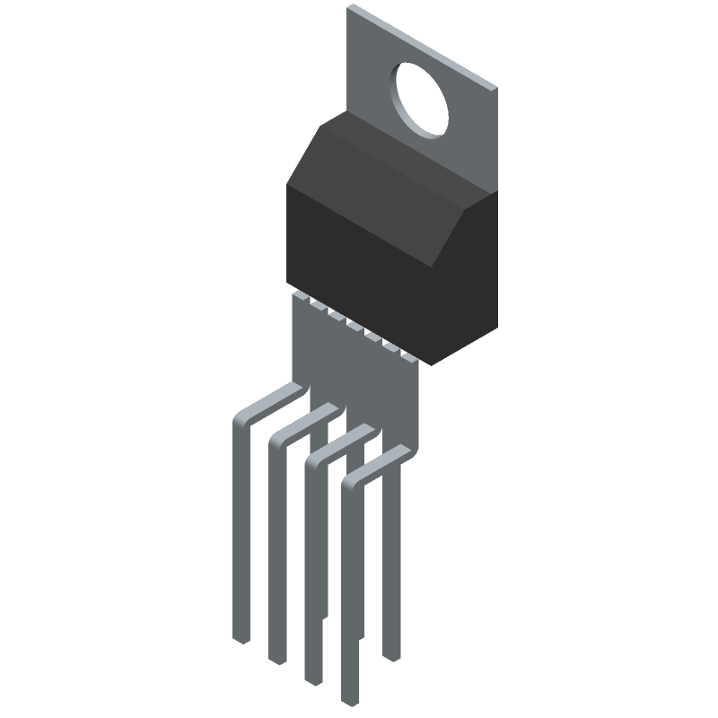
3D Model
Available Download Formats
By downloading CAD models, you agree to our Terms & Conditions and Privacy Policy

PWM Solenoid/Valve Driver 7-TO-220 -55 to 125
Tip: Data for a part may vary between manufacturers. You can filter for manufacturers on the top of the page next to the part image and part number.
DRV102TG3 by Texas Instruments is a Peripheral Driver.
Peripheral Drivers are under the broader part category of Drivers And Interfaces.
A driver controls the current or voltage delivered to components like LCDs or motors, while an interface component connects systems for data transfer and control. Read more about Drivers And Interfaces on our Drivers And Interfaces part category page.
| Part # | Distributor | Description | Stock | Price | Buy | |
|---|---|---|---|---|---|---|
|
|
Vyrian | Interface ICs | 1400 |
|
RFQ |
By downloading CAD models, you agree to our Terms & Conditions and Privacy Policy
|
|
DRV102TG3
Texas Instruments
Buy Now
Datasheet
|
Compare Parts:
DRV102TG3
Texas Instruments
PWM Solenoid/Valve Driver 7-TO-220 -55 to 125
|
| Rohs Code | Yes | |
| Part Life Cycle Code | Obsolete | |
| Ihs Manufacturer | TEXAS INSTRUMENTS INC | |
| Part Package Code | SFM | |
| Package Description | TO-220, 7 PIN | |
| Pin Count | 3 | |
| Reach Compliance Code | compliant | |
| ECCN Code | EAR99 | |
| HTS Code | 8542.39.00.01 | |
| Samacsys Manufacturer | Texas Instruments | |
| Built-in Protections | OVER CURRENT; THERMAL | |
| Driver Number of Bits | 1 | |
| Interface IC Type | BUFFER OR INVERTER BASED PERIPHERAL DRIVER | |
| JESD-30 Code | R-PZFM-T7 | |
| JESD-609 Code | e3 | |
| Number of Functions | 1 | |
| Number of Terminals | 7 | |
| Operating Temperature-Max | 125 °C | |
| Operating Temperature-Min | -55 °C | |
| Output Current Flow Direction | SOURCE | |
| Output Current-Max | 1 A | |
| Output Peak Current Limit-Nom | 2.7 A | |
| Package Body Material | PLASTIC/EPOXY | |
| Package Code | ZFM | |
| Package Equivalence Code | ZIP7,.15,.2TB | |
| Package Shape | RECTANGULAR | |
| Package Style | FLANGE MOUNT | |
| Qualification Status | Not Qualified | |
| Supply Voltage-Max | 60 V | |
| Supply Voltage-Min | 8 V | |
| Supply Voltage-Nom | 24 V | |
| Surface Mount | NO | |
| Technology | BIPOLAR | |
| Temperature Grade | MILITARY | |
| Terminal Finish | MATTE TIN | |
| Terminal Form | THROUGH-HOLE | |
| Terminal Pitch | 1.27 mm | |
| Terminal Position | ZIG-ZAG |
A good PCB layout for the DRV102TG3 involves keeping the high-current paths short and wide, using a solid ground plane, and placing the input and output capacitors close to the device. TI provides a recommended PCB layout in the datasheet and application notes.
Choose input and output capacitors with low ESR, high ripple current rating, and a voltage rating that exceeds the maximum input and output voltages. X5R or X7R ceramic capacitors or film capacitors are good options. The datasheet provides guidance on capacitor selection.
The maximum ambient temperature for the DRV102TG3 is 85°C. However, the device can operate at higher temperatures with derating. Consult the datasheet for thermal derating curves.
Use a voltage supervisor or a voltage monitor IC to detect overvoltage and undervoltage conditions. You can also add external overvoltage protection (OVP) and undervoltage protection (UVP) circuits to prevent damage to the DRV102TG3.
The recommended input voltage range for the DRV102TG3 is 4.5V to 18V. However, the device can operate with input voltages as low as 3.5V and as high as 20V, but with reduced performance and efficiency.