-
Part Symbol
-
Footprint
-
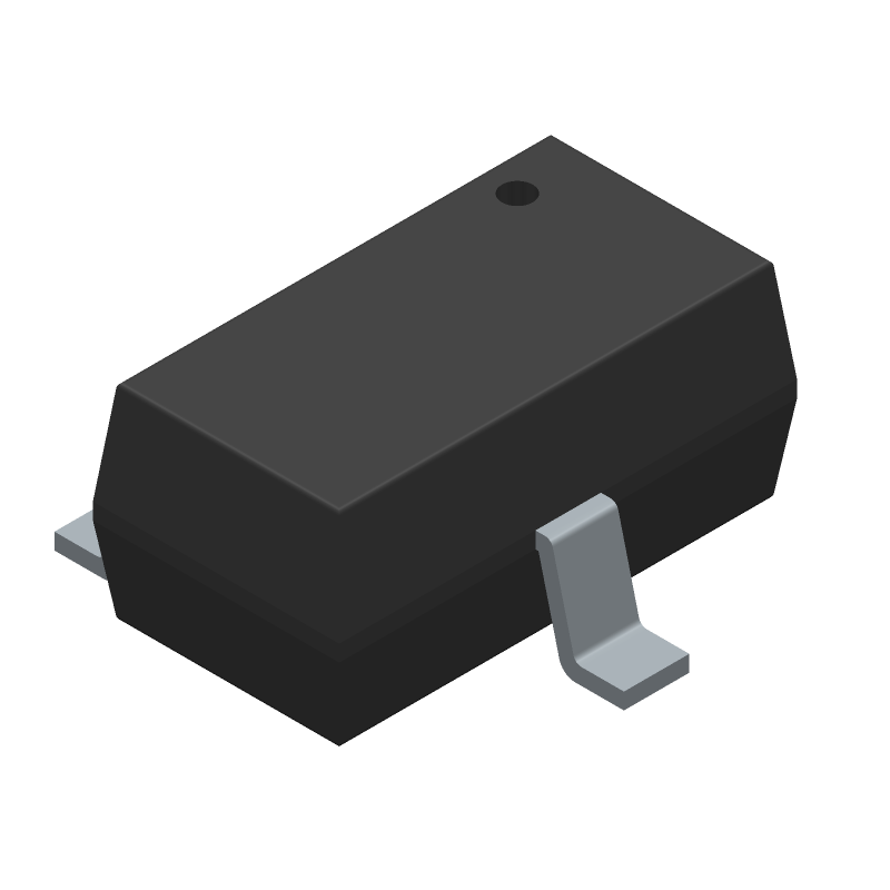
3D Model
Available Download Formats
By downloading CAD models, you agree to our Terms & Conditions and Privacy Policy
Small Signal Bipolar Transistor, 0.1A I(C), 50V V(BR)CEO, 1-Element, NPN, Silicon, TO-236AA, HALOGEN FREE AND ROHS COMPLIANT, MINI3-G3-B, SC-59A, 3 PIN
Tip: Data for a part may vary between manufacturers. You can filter for manufacturers on the top of the page next to the part image and part number.
DRC2115T0L by Panasonic Electronic Components is a Small Signal Bipolar Transistor.
Small Signal Bipolar Transistors are under the broader part category of Transistors.
A transistor is a small semiconductor device used to amplify, control, or create electrical signals. When selecting a transistor, factors such as voltage, current rating, gain, and power dissipation must be considered, with common types. Read more about Transistors on our Transistors part category page.
By downloading CAD models, you agree to our Terms & Conditions and Privacy Policy
|
|
DRC2115T0L
Panasonic Electronic Components
Buy Now
Datasheet
|
Compare Parts:
DRC2115T0L
Panasonic Electronic Components
Small Signal Bipolar Transistor, 0.1A I(C), 50V V(BR)CEO, 1-Element, NPN, Silicon, TO-236AA, HALOGEN FREE AND ROHS COMPLIANT, MINI3-G3-B, SC-59A, 3 PIN
|
| Rohs Code | Yes | |
| Part Life Cycle Code | Transferred | |
| Ihs Manufacturer | PANASONIC CORP | |
| Package Description | HALOGEN FREE AND ROHS COMPLIANT, MINI3-G3-B, SC-59A, 3 PIN | |
| Reach Compliance Code | unknown | |
| ECCN Code | EAR99 | |
| Samacsys Manufacturer | Panasonic | |
| Collector Current-Max (IC) | 0.1 A | |
| Collector-Emitter Voltage-Max | 50 V | |
| Configuration | SINGLE WITH BUILT-IN RESISTOR | |
| DC Current Gain-Min (hFE) | 160 | |
| JEDEC-95 Code | TO-236AA | |
| JESD-30 Code | R-PDSO-G3 | |
| Number of Elements | 1 | |
| Number of Terminals | 3 | |
| Package Body Material | PLASTIC/EPOXY | |
| Package Shape | RECTANGULAR | |
| Package Style | SMALL OUTLINE | |
| Peak Reflow Temperature (Cel) | NOT SPECIFIED | |
| Polarity/Channel Type | NPN | |
| Surface Mount | YES | |
| Terminal Form | GULL WING | |
| Terminal Position | DUAL | |
| Time@Peak Reflow Temperature-Max (s) | NOT SPECIFIED | |
| Transistor Application | SWITCHING | |
| Transistor Element Material | SILICON |
Panasonic recommends a 4-layer PCB with a solid ground plane, and to keep the input and output traces as short as possible. Additionally, it's recommended to use a common mode choke or a ferrite bead to filter out high-frequency noise.
To ensure reliability, it's essential to follow the recommended derating guidelines for temperature and power dissipation. Additionally, consider using a heat sink or thermal interface material to reduce the junction temperature. It's also recommended to perform thermal simulations and testing to validate the design.
Although the datasheet doesn't explicitly state the maximum allowed voltage, it's generally recommended to keep the input and output voltages within the specified operating range (±15% of the rated voltage) to prevent damage or malfunction.
Yes, the DRC2115T0L is suitable for switching power supply applications due to its high-frequency characteristics and low ESR. However, it's essential to follow the recommended layout and design guidelines to minimize electromagnetic interference (EMI) and ensure reliable operation.
To minimize EMI and radiation, follow the recommended PCB layout and design guidelines, such as keeping the input and output traces short and using a common mode choke or ferrite bead. Additionally, consider using shielding or a metal enclosure to contain the EMI radiation.