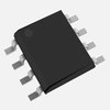
Part Details for CS4334-KSZR by Cirrus Logic
Results Overview of CS4334-KSZR by Cirrus Logic
- Distributor Offerings: (7 listings)
- Number of FFF Equivalents: (0 replacements)
- CAD Models: (Request Part)
- Number of Functional Equivalents: (0 options)
- Part Data Attributes: (Available)
- Reference Designs: (Not Available)
Tip: Data for a part may vary between manufacturers. You can filter for manufacturers on the top of the page next to the part image and part number.
CS4334-KSZR Information
CS4334-KSZR by Cirrus Logic is a Digital to Analog Converter.
Digital to Analog Converters are under the broader part category of Converters.
A converter is an electrical circuit that transforms electric energy into a different form that will support a elecrical load needed by a device. Read more about Converters on our Converters part category page.
Price & Stock for CS4334-KSZR
| Part # | Distributor | Description | Stock | Price | Buy | |
|---|---|---|---|---|---|---|
|
|
Bristol Electronics | 35452 |
|
RFQ | ||
|
|
Quest Components | D/A CONVERTER, 1 FUNC, SERIAL INPUT LOADING, PDSO8 | 333 |
|
$3.3000 / $6.0000 | Buy Now |
|
|
Chip 1 Exchange | INSTOCK | 2887 |
|
RFQ | |
|
DISTI #
CS4334-KSZR
|
Avnet Silica | Digital to Analog Converter 2 Channels 24 bit Filtered Stereo Voltage Serial 475 V to 55 V 8 Pins PSOIC (Alt: CS4334-KSZR) RoHS: Compliant Min Qty: 3000 Package Multiple: 3000 | Silica - 0 |
|
Buy Now | |
|
|
New Advantage Corporation | CBM-75B SERIES 2400 RoHS: Compliant Min Qty: 1 Package Multiple: 1 | 999 |
|
$2.9000 | Buy Now |
|
|
Vyrian | Converters | 682 |
|
RFQ | |
|
|
Win Source Electronics | IC DAC STER 24BIT 96KHZ 8-SOIC | 22740 |
|
$0.5391 / $0.6962 | Buy Now |
Part Details for CS4334-KSZR
CS4334-KSZR CAD Models
CS4334-KSZR Part Data Attributes
|
|
CS4334-KSZR
Cirrus Logic
Buy Now
Datasheet
|
Compare Parts:
CS4334-KSZR
Cirrus Logic
D/A Converter, 1 Func, Serial Input Loading, PDSO8, 0.150 INCH, LEAD FREE, PLASTIC, MS-012, SOIC-8
|
| Pbfree Code | Yes | |
| Rohs Code | Yes | |
| Part Life Cycle Code | Obsolete | |
| Ihs Manufacturer | CIRRUS LOGIC INC | |
| Part Package Code | SOIC | |
| Package Description | 0.150 INCH, LEAD FREE, PLASTIC, MS-012, SOIC-8 | |
| Pin Count | 8 | |
| Reach Compliance Code | compliant | |
| HTS Code | 8542.39.00.01 | |
| Samacsys Manufacturer | Cirrus Logic | |
| Analog Output Voltage-Max | 3.75 V | |
| Analog Output Voltage-Min | -3.75 V | |
| Converter Type | D/A CONVERTER | |
| Input Bit Code | 2'S COMPLEMENT BINARY | |
| Input Format | SERIAL | |
| JESD-30 Code | R-PDSO-G8 | |
| JESD-609 Code | e3 | |
| Length | 4.9 mm | |
| Moisture Sensitivity Level | 2 | |
| Number of Bits | 24 | |
| Number of Functions | 1 | |
| Number of Terminals | 8 | |
| Operating Temperature-Max | 70 °C | |
| Operating Temperature-Min | -10 °C | |
| Package Body Material | PLASTIC/EPOXY | |
| Package Code | SOP | |
| Package Equivalence Code | SOP8,.25 | |
| Package Shape | RECTANGULAR | |
| Package Style | SMALL OUTLINE | |
| Peak Reflow Temperature (Cel) | 260 | |
| Qualification Status | Not Qualified | |
| Seated Height-Max | 1.75 mm | |
| Supply Current-Max | 19 mA | |
| Supply Voltage-Nom | 5 V | |
| Surface Mount | YES | |
| Technology | BIPOLAR | |
| Temperature Grade | COMMERCIAL | |
| Terminal Finish | MATTE TIN | |
| Terminal Form | GULL WING | |
| Terminal Pitch | 1.27 mm | |
| Terminal Position | DUAL | |
| Width | 3.9 mm |
CS4334-KSZR Frequently Asked Questions (FAQ)
-
The recommended power-up sequence is to apply VDD first, followed by VDDIO, and then the clock signal. This ensures proper device initialization and prevents potential latch-up conditions.
-
To configure the CS4334-KSZR for master clock mode, set the MCLK pin as the clock source, and ensure that the MCLK frequency is within the recommended range of 10-50 MHz. Additionally, set the BCLK pin to the desired bit clock frequency.
-
The maximum allowed capacitance for the analog output filters is 10 nF. Exceeding this value may affect the device's performance and stability.
-
To optimize the ADC performance, ensure that the analog input signals are within the recommended voltage range, and that the ADC clock frequency is set to the recommended value of 256 fs. Additionally, use a low-pass filter to remove high-frequency noise from the analog input signals.
-
To minimize noise and interference, keep digital and analog signals separate, and use a multi-layer PCB with a dedicated ground plane. Route digital signals away from analog signals, and use shielding or guard rings to reduce electromagnetic interference (EMI).
