-
Part Symbol
-
Footprint
-
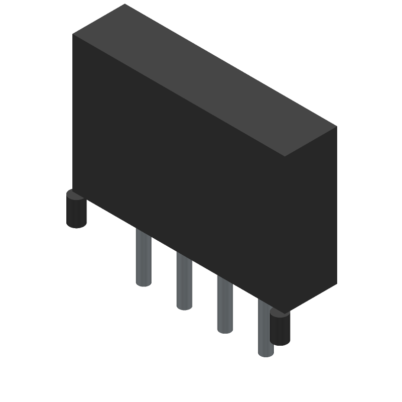
3D Model
Available Download Formats
By downloading CAD models, you agree to our Terms & Conditions and Privacy Policy
Board Connector, 4 Contact(s), 2 Row(s), Male, Straight, Solder Terminal, ROHS COMPLIANT
Tip: Data for a part may vary between manufacturers. You can filter for manufacturers on the top of the page next to the part image and part number.
CP3504P1V00 by Cvilux Corporation is a Header and Edge Type Connector.
Headers and Edge Type Connectors are under the broader part category of Connectors.
Connectors are devices that join electrical termination points to form circuits. With various types designed for specific functions like data, power, or signal transmission, choosing the right connector is essential for compatibility and device performance. Read more about Connectors on our Connectors part category page.
| Part # | Distributor | Description | Stock | Price | Buy | |
|---|---|---|---|---|---|---|
|
DISTI #
CP3504P1V00
|
Avnet Americas | CVLCP3504P1V00 - Trays (Alt: CP3504P1V00) RoHS: Compliant Min Qty: 2040 Package Multiple: 120 Lead time: 111 Weeks, 0 Days Container: Tray | 0 |
|
$0.1194 / $0.1638 | Buy Now |
|
DISTI #
CP3504P1V00
|
Avnet Abacus | CVLCP3504P1V00 (Alt: CP3504P1V00) RoHS: Compliant Min Qty: 2040 Package Multiple: 120 Lead time: 17 Weeks, 0 Days | Abacus - 2040 |
|
Buy Now |
By downloading CAD models, you agree to our Terms & Conditions and Privacy Policy
|
|
CP3504P1V00
Cvilux Corporation
Buy Now
Datasheet
|
Compare Parts:
CP3504P1V00
Cvilux Corporation
Board Connector, 4 Contact(s), 2 Row(s), Male, Straight, Solder Terminal, ROHS COMPLIANT
|
| Pbfree Code | Yes | |
| Rohs Code | Yes | |
| Part Life Cycle Code | Active | |
| Ihs Manufacturer | CVILUX CORP | |
| Package Description | ROHS COMPLIANT | |
| Reach Compliance Code | compliant | |
| ECCN Code | EAR99 | |
| HTS Code | 8536.69.40.40 | |
| Factory Lead Time | 111 Weeks | |
| Samacsys Manufacturer | CviLux Corporation | |
| Additional Feature | SHROUDED | |
| Connector Type | BOARD CONNECTOR | |
| Contact Finish Mating | TIN OVER NICKEL | |
| Contact Finish Termination | TIN OVER NICKEL | |
| Contact Gender | MALE | |
| Contact Material | NOT SPECIFIED | |
| DIN Conformance | NO | |
| Filter Feature | NO | |
| IEC Conformance | NO | |
| JESD-609 Code | e3 | |
| MIL Conformance | NO | |
| Mating Information | MULTIPLE MATING PARTS AVAILABLE | |
| Mixed Contacts | NO | |
| Mounting Style | STRAIGHT | |
| Mounting Type | BOARD | |
| Number Of Connectors | ONE | |
| Number of Rows Loaded | 2 | |
| Option | GENERAL PURPOSE | |
| Terminal Pitch | 3 mm | |
| Termination Type | SOLDER | |
| Total Number of Contacts | 4 | |
| UL Flammability Code | 94V-0 |
The recommended operating temperature range for the CP3504P1V00 is -40°C to 85°C, as specified in the datasheet. However, it's essential to note that the device's performance and reliability may degrade if operated outside this range for extended periods.
To ensure proper soldering, follow the recommended soldering profile and temperature guidelines provided in the datasheet. Additionally, use a solder with a melting point compatible with the device's lead-free finish, and avoid applying excessive heat or mechanical stress during the soldering process.
While the datasheet specifies the recommended operating voltage range, it's essential to note that the maximum allowable voltage for the input pins is typically 10% to 15% above the recommended voltage. However, it's crucial to consult with the manufacturer or a qualified engineer to determine the exact maximum voltage tolerance for your specific application.
To troubleshoot issues with the CP3504P1V00, start by reviewing the datasheet and application notes to ensure proper usage and configuration. Next, verify the power supply and signal integrity, and check for any signs of physical damage or overheating. If the issue persists, consult with the manufacturer's technical support or a qualified engineer for further assistance.
Yes, the CP3504P1V00 has specific layout and routing requirements to ensure optimal performance and minimize electromagnetic interference (EMI). Follow the recommended PCB layout guidelines provided in the datasheet or application notes, and consult with a qualified engineer or the manufacturer's technical support if you're unsure about any aspect of the design.