-
Part Symbol
-
Footprint
-
3D Model
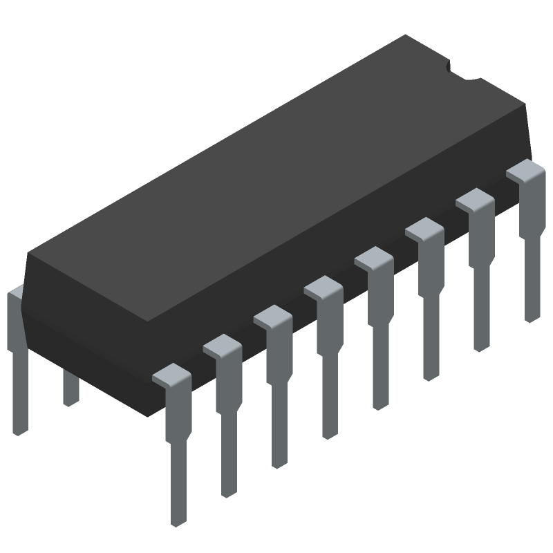
Available Download Formats
By downloading CAD models, you agree to our Terms & Conditions and Privacy Policy
Binary Counter, 4000/14000/40000 Series, Synchronous, Positive Edge Triggered, 4-Bit, Up Direction, CMOS, PDIP16
Tip: Data for a part may vary between manufacturers. You can filter for manufacturers on the top of the page next to the part image and part number.
CD4520BE by Harris Semiconductor is a Counter.
Counters are under the broader part category of Logic Components.
Digital logic governs the behavior of signals in electronic circuits, enabling complex decisions based on simple binary inputs (yes/no). Logic components perform operations from these signals. Read more about Logic Components on our Logic part category page.
| Part # | Manufacturer | Description | Datasheet |
|---|---|---|---|
| CD4520BEE4 | Texas Instruments | CMOS Dual Binary Up-Counter 16-PDIP -55 to 125 | |
| CD4520BE | Texas Instruments | CMOS Dual Binary Up-Counter 16-PDIP -55 to 125 |
| Part # | Distributor | Description | Stock | Price | Buy | |
|---|---|---|---|---|---|---|
|
|
Bristol Electronics | 145 |
|
RFQ | ||
|
|
Quest Components | IC,COUNTER,UP,4-BIT BINARY,CMOS,DIP,16PIN,PLASTIC | 7 |
|
$0.6530 / $0.7836 | Buy Now |
By downloading CAD models, you agree to our Terms & Conditions and Privacy Policy
|
|
CD4520BE
Harris Semiconductor
Buy Now
Datasheet
|
Compare Parts:
CD4520BE
Harris Semiconductor
Binary Counter, 4000/14000/40000 Series, Synchronous, Positive Edge Triggered, 4-Bit, Up Direction, CMOS, PDIP16
|
| Rohs Code | No | |
| Part Life Cycle Code | Transferred | |
| Ihs Manufacturer | HARRIS SEMICONDUCTOR | |
| Package Description | DIP-16 | |
| Reach Compliance Code | unknown | |
| HTS Code | 8542.39.00.01 | |
| Samacsys Manufacturer | Harris | |
| Additional Feature | GATED CLOCK; SCHMITT TRIGGER ON CLOCK INPUT | |
| Count Direction | UP | |
| Family | 4000/14000/40000 | |
| JESD-30 Code | R-PDIP-T16 | |
| JESD-609 Code | e0 | |
| Load Capacitance (CL) | 50 pF | |
| Load/Preset Input | NO | |
| Logic IC Type | BINARY COUNTER | |
| Max Frequency@Nom-Sup | 1500000 Hz | |
| Max I(ol) | 0.00041999999999999996 A | |
| Mode of Operation | SYNCHRONOUS | |
| Number of Bits | 4 | |
| Number of Functions | 2 | |
| Number of Terminals | 16 | |
| Operating Temperature-Max | 125 °C | |
| Operating Temperature-Min | -55 °C | |
| Package Body Material | PLASTIC/EPOXY | |
| Package Code | DIP | |
| Package Equivalence Code | DIP16,.3 | |
| Package Shape | RECTANGULAR | |
| Package Style | IN-LINE | |
| Qualification Status | Not Qualified | |
| Supply Voltage-Max (Vsup) | 18 V | |
| Supply Voltage-Min (Vsup) | 3 V | |
| Supply Voltage-Nom (Vsup) | 5 V | |
| Surface Mount | NO | |
| Technology | CMOS | |
| Temperature Grade | MILITARY | |
| Terminal Finish | Tin/Lead (Sn/Pb) | |
| Terminal Form | THROUGH-HOLE | |
| Terminal Pitch | 2.54 mm | |
| Terminal Position | DUAL | |
| Trigger Type | POSITIVE EDGE |
The recommended operating voltage range for the CD4520BE is 3V to 18V, although it can operate up to 20V with reduced performance.
To ensure proper power-on and power-off, the VCC pin should be ramped up and down slowly (typically 1-10 ms) to prevent voltage spikes and latch-up.
The maximum clock frequency that the CD4520BE can handle is 10 MHz, although this may vary depending on the specific application and operating conditions.
The asynchronous reset input (MR) should be tied to VCC through a pull-up resistor (typically 1kΩ to 10kΩ) to ensure proper reset operation.
The output drive capability of the CD4520BE is typically 1.5 mA per output pin, although this may vary depending on the specific application and operating conditions.