-
Part Symbol
-
Footprint
-
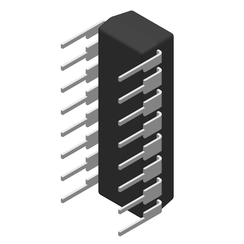
3D Model
Available Download Formats
By downloading CAD models, you agree to our Terms & Conditions and Privacy Policy

CMOS 21-Stage Counter 16-PDIP -55 to 125
Tip: Data for a part may vary between manufacturers. You can filter for manufacturers on the top of the page next to the part image and part number.
CD4045BE by Texas Instruments is a Counter.
Counters are under the broader part category of Logic Components.
Digital logic governs the behavior of signals in electronic circuits, enabling complex decisions based on simple binary inputs (yes/no). Logic components perform operations from these signals. Read more about Logic Components on our Logic part category page.
| Part # | Distributor | Description | Stock | Price | Buy | |
|---|---|---|---|---|---|---|
|
DISTI #
296-3512-5-ND
|
DigiKey | IC BINARY COUNTER 21-BIT 16DIP Min Qty: 1 Lead time: 18 Weeks Container: Tube |
1877 In Stock |
|
$0.5313 / $1.1300 | Buy Now |
|
DISTI #
595-CD4045BE
|
Mouser Electronics | Counter ICs 21-Stage RoHS: Compliant | 2602 |
|
$0.5070 / $1.1300 | Buy Now |
|
DISTI #
86277403
|
Verical | Counter Single 21-Bit Binary UP 16-Pin PDIP Tube RoHS: Compliant Min Qty: 459 Package Multiple: 1 Date Code: 1201 | Americas - 4175 |
|
$0.8171 | Buy Now |
|
DISTI #
86277220
|
Verical | Counter Single 21-Bit Binary UP 16-Pin PDIP Tube RoHS: Compliant Min Qty: 459 Package Multiple: 1 Date Code: 1001 | Americas - 1100 |
|
$0.8171 | Buy Now |
|
DISTI #
88041560
|
Verical | Counter Single 21-Bit Binary UP 16-Pin PDIP Tube RoHS: Compliant Min Qty: 459 Package Multiple: 1 | Americas - 500 |
|
$0.8171 | Buy Now |
|
|
Quest Components | IC,COUNTER,UP,21-BIT BINARY,CMOS,DIP,16PIN,PLASTIC | 10 |
|
$0.3900 | Buy Now |
|
|
Rochester Electronics | CD4045B CMOS 21-Stage Counter RoHS: Compliant Status: Active Min Qty: 1 | 6323 |
|
$0.4053 / $0.6537 | Buy Now |
By downloading CAD models, you agree to our Terms & Conditions and Privacy Policy
|
|
CD4045BE
Texas Instruments
Buy Now
Datasheet
|
Compare Parts:
CD4045BE
Texas Instruments
CMOS 21-Stage Counter 16-PDIP -55 to 125
|
| Rohs Code | Yes | |
| Part Life Cycle Code | Active | |
| Ihs Manufacturer | TEXAS INSTRUMENTS INC | |
| Part Package Code | DIP | |
| Package Description | ROHS COMPLIANT, PLASTIC, DIP-16 | |
| Pin Count | 16 | |
| Reach Compliance Code | compliant | |
| ECCN Code | EAR99 | |
| HTS Code | 8542.39.00.01 | |
| Samacsys Manufacturer | Texas Instruments | |
| Count Direction | UP | |
| Family | 4000/14000/40000 | |
| JESD-30 Code | R-PDIP-T16 | |
| JESD-609 Code | e4 | |
| Length | 19.305 mm | |
| Load Capacitance (CL) | 50 pF | |
| Load/Preset Input | YES | |
| Logic IC Type | DIVIDE BY N COUNTER | |
| Max Frequency@Nom-Sup | 5000000 Hz | |
| Max I(ol) | 0.0105 A | |
| Mode of Operation | SYNCHRONOUS | |
| Number of Bits | 21 | |
| Number of Functions | 1 | |
| Number of Terminals | 16 | |
| Operating Temperature-Max | 125 °C | |
| Operating Temperature-Min | -55 °C | |
| Package Body Material | PLASTIC/EPOXY | |
| Package Code | DIP | |
| Package Equivalence Code | DIP16,.3 | |
| Package Shape | RECTANGULAR | |
| Package Style | IN-LINE | |
| Packing Method | TUBE | |
| Power Supply Current-Max (ICC) | 0.03 mA | |
| Prop. Delay@Nom-Sup | 2700 ns | |
| Propagation Delay (tpd) | 5500 ns | |
| Qualification Status | Not Qualified | |
| Seated Height-Max | 5.08 mm | |
| Supply Voltage-Max (Vsup) | 18 V | |
| Supply Voltage-Min (Vsup) | 3 V | |
| Supply Voltage-Nom (Vsup) | 5 V | |
| Surface Mount | NO | |
| Technology | CMOS | |
| Temperature Grade | MILITARY | |
| Terminal Finish | Nickel/Palladium/Gold (Ni/Pd/Au) | |
| Terminal Form | THROUGH-HOLE | |
| Terminal Pitch | 2.54 mm | |
| Terminal Position | DUAL | |
| Trigger Type | POSITIVE EDGE | |
| Width | 7.62 mm | |
| fmax-Min | 45 MHz |
The recommended operating voltage range for the CD4045BE is 4.5V to 15V.
To ensure the oscillator starts reliably, a 1kΩ to 10kΩ resistor should be connected between the oscillator pins (pins 11 and 12) and a 10nF to 100nF capacitor should be connected between the oscillator pin (pin 11) and ground.
The maximum frequency of operation for the CD4045BE is approximately 1MHz.
To synchronize the CD4045BE with an external clock signal, connect the external clock signal to the clock input pin (pin 1) and set the oscillator disable pin (pin 13) to a logic high level.
The VDD pin (pin 16) is the power supply pin for the internal logic circuits and should be connected to a stable voltage source.