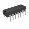
Part Details for CD4013BF/3 by RCA
Results Overview of CD4013BF/3 by RCA
- Distributor Offerings: (3 listings)
- Number of FFF Equivalents: (0 replacements)
- CAD Models: (Request Part)
- Number of Functional Equivalents: (0 options)
- Part Data Attributes: (Available)
- Reference Designs: (Not Available)
Tip: Data for a part may vary between manufacturers. You can filter for manufacturers on the top of the page next to the part image and part number.
CD4013BF/3 Information
CD4013BF/3 by RCA is an FF/Latch.
FF/Latches are under the broader part category of Logic Components.
Digital logic governs the behavior of signals in electronic circuits, enabling complex decisions based on simple binary inputs (yes/no). Logic components perform operations from these signals. Read more about Logic Components on our Logic part category page.
Price & Stock for CD4013BF/3
| Part # | Distributor | Description | Stock | Price | Buy | |
|---|---|---|---|---|---|---|
|
|
Bristol Electronics | 56 |
|
RFQ | ||
|
|
Bristol Electronics | 3 |
|
RFQ | ||
|
|
Quest Components | IC,FLIP-FLOP,DUAL,D TYPE,CMOS,DIP,14PIN,CERAMIC | 44 |
|
$15.4475 / $18.7875 | Buy Now |
Part Details for CD4013BF/3
CD4013BF/3 CAD Models
CD4013BF/3 Part Data Attributes
|
|
CD4013BF/3
RCA
Buy Now
Datasheet
|
Compare Parts:
CD4013BF/3
RCA
D Flip-Flop, 4000/14000/40000 Series, 2-Func, Positive Edge Triggered, 1-Bit, Complementary Output, CMOS, CDIP14, HERMETIC SEALED, CERAMIC, DIP-14
|
| Pbfree Code | No | |
| Rohs Code | No | |
| Part Life Cycle Code | Obsolete | |
| Ihs Manufacturer | RCA SOLID STATE | |
| Part Package Code | DIP | |
| Package Description | HERMETIC SEALED, CERAMIC, DIP-14 | |
| Pin Count | 14 | |
| Reach Compliance Code | unknown | |
| HTS Code | 8542.39.00.01 | |
| Family | 4000/14000/40000 | |
| JESD-30 Code | R-GDIP-T14 | |
| JESD-609 Code | e0 | |
| Logic IC Type | D FLIP-FLOP | |
| Number of Bits | 1 | |
| Number of Functions | 2 | |
| Number of Terminals | 14 | |
| Operating Temperature-Max | 125 °C | |
| Operating Temperature-Min | -55 °C | |
| Output Polarity | COMPLEMENTARY | |
| Package Body Material | CERAMIC, GLASS-SEALED | |
| Package Code | DIP | |
| Package Equivalence Code | DIP14,.3 | |
| Package Shape | RECTANGULAR | |
| Package Style | IN-LINE | |
| Prop. Delay@Nom-Sup | 400 ns | |
| Propagation Delay (tpd) | 300 ns | |
| Qualification Status | Not Qualified | |
| Screening Level | MIL-STD-883 Class B (Modified) | |
| Supply Voltage-Max (Vsup) | 18 V | |
| Supply Voltage-Min (Vsup) | 3 V | |
| Supply Voltage-Nom (Vsup) | 5 V | |
| Surface Mount | NO | |
| Technology | CMOS | |
| Temperature Grade | MILITARY | |
| Terminal Finish | TIN LEAD | |
| Terminal Form | THROUGH-HOLE | |
| Terminal Pitch | 2.54 mm | |
| Terminal Position | DUAL | |
| Trigger Type | POSITIVE EDGE |
CD4013BF/3 Frequently Asked Questions (FAQ)
-
The recommended operating voltage range for CD4013BF/3 is 5V to 15V, with a typical operating voltage of 12V.
-
To prevent clock skew, it's recommended to use a clock signal with a rise time of less than 10ns and a fall time of less than 10ns. Additionally, the clock input should be driven from a low-impedance source, and the clock signal should be routed close to the device to minimize signal degradation.
-
The maximum clock frequency that CD4013BF/3 can handle is 10MHz. However, the actual clock frequency limit may be lower depending on the specific application and operating conditions.
-
To ensure that the device is properly reset during power-up, it's recommended to connect the Reset (R) input to a pull-up resistor and a capacitor to VCC. This will ensure that the device is reset to a known state during power-up.
-
The maximum output current that CD4013BF/3 can sink or source is 1.5mA. Exceeding this current limit may cause device damage or malfunction.
