-
Part Symbol
-
Footprint
-
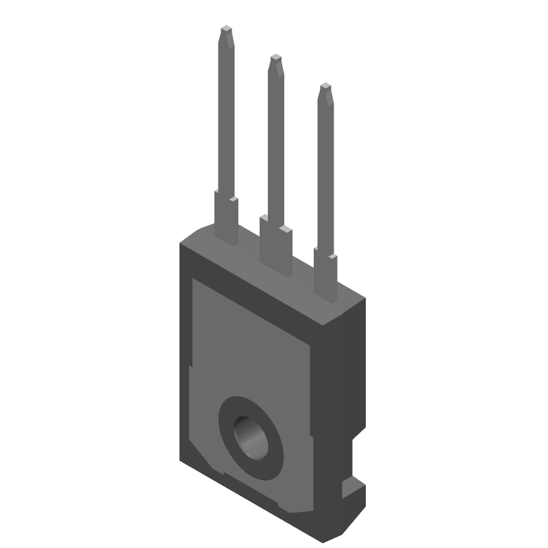
3D Model
Available Download Formats
By downloading CAD models, you agree to our Terms & Conditions and Privacy Policy

MOSFET N-CH 1700V 4.9A TO247
Tip: Data for a part may vary between manufacturers. You can filter for manufacturers on the top of the page next to the part image and part number.
C2M1000170D by Wolfspeed is a Power Field-Effect Transistor.
Power Field-Effect Transistors are under the broader part category of Transistors.
A transistor is a small semiconductor device used to amplify, control, or create electrical signals. When selecting a transistor, factors such as voltage, current rating, gain, and power dissipation must be considered, with common types. Read more about Transistors on our Transistors part category page.
| Part # | Distributor | Description | Stock | Price | Buy | |
|---|---|---|---|---|---|---|
|
DISTI #
12X8366
|
Newark | Sic Mosfet, N-Ch, 1.7Kv, 4.9A, To-247, Mosfet Module Configuration:Single, Channel Type:N Channel, Continuous Drain Current Id:4.9A, Drain Source Voltage Vds:1.7Kv, No. Of Pins:3Pins, Rds(On) Test Voltage:20V, Power Dissipation:69W Rohs Compliant: Yes |Wolfspeed C2M1000170D RoHS: Compliant Min Qty: 1 Package Multiple: 1 Date Code: 0 Container: Bulk | 0 |
|
$8.4400 / $11.8200 | Buy Now |
|
DISTI #
C2M1000170D
|
TME | Transistor: N-MOSFET, SiC, unipolar, 1.7kV, 4.9A, 69W, TO247-3, 20ns Min Qty: 1 | 106 |
|
$6.7300 / $10.9700 | Buy Now |
|
DISTI #
C2M1000170D
|
Richardson RFPD | SILICON CARBIDE MOSFETS RoHS: Compliant Min Qty: 1 | 0 |
|
$5.8300 / $6.0900 | Buy Now |
|
|
Win Source Electronics | 900 |
|
$25.4546 / $38.1818 | Buy Now |
By downloading CAD models, you agree to our Terms & Conditions and Privacy Policy
|
|
C2M1000170D
Wolfspeed
Buy Now
Datasheet
|
Compare Parts:
C2M1000170D
Wolfspeed
MOSFET N-CH 1700V 4.9A TO247
|
| Pbfree Code | Yes | |
| Rohs Code | Yes | |
| Part Life Cycle Code | Obsolete | |
| Ihs Manufacturer | WOLFSPEED INC | |
| Reach Compliance Code | not_compliant | |
| ECCN Code | EAR99 | |
| Samacsys Manufacturer | Wolfspeed | |
| Additional Feature | HIGH RELIABILITY | |
| Configuration | SINGLE WITH BUILT-IN DIODE | |
| DS Breakdown Voltage-Min | 1700 V | |
| Drain Current-Max (ID) | 4.9 A | |
| Drain-source On Resistance-Max | 1.1 Ω | |
| FET Technology | METAL-OXIDE SEMICONDUCTOR | |
| JEDEC-95 Code | TO-247AD | |
| JESD-30 Code | R-PSFM-T3 | |
| JESD-609 Code | e3 | |
| Number of Elements | 1 | |
| Number of Terminals | 3 | |
| Operating Mode | ENHANCEMENT MODE | |
| Package Body Material | PLASTIC/EPOXY | |
| Package Shape | RECTANGULAR | |
| Package Style | FLANGE MOUNT | |
| Peak Reflow Temperature (Cel) | 260 | |
| Polarity/Channel Type | N-CHANNEL | |
| Pulsed Drain Current-Max (IDM) | 5 A | |
| Surface Mount | NO | |
| Terminal Finish | Tin (Sn) | |
| Terminal Form | THROUGH-HOLE | |
| Terminal Position | SINGLE | |
| Time@Peak Reflow Temperature-Max (s) | 10 | |
| Transistor Application | SWITCHING | |
| Transistor Element Material | SILICON |
A 2-layer or 4-layer PCB with a thermal via array underneath the device is recommended. The thermal vias should be connected to a solid copper plane on the bottom layer to dissipate heat efficiently.
Ensure proper heat sinking, use a thermally conductive interface material, and follow the recommended PCB layout. Also, derate the device's power handling capability according to the temperature derating curve in the datasheet.
A gate driver with a high current capability (e.g., 2A) and a low output impedance is recommended. The gate drive circuitry should also include a resistor in series with the gate to limit the current and prevent oscillations.
Use a voltage clamp or a zener diode to protect the device from overvoltage. For overcurrent protection, use a current sense resistor and a comparator or a dedicated overcurrent protection IC.
Use a wire bonding technique with a 1-mil aluminum wire or a gold wire. For soldering, use a solder with a high melting point (e.g., 96.5Sn/3Ag/0.5Cu) and follow the recommended soldering profile to prevent thermal damage.